Sony XAV-602BT Installation Guide 1 - Page 1
Sony XAV-602BT Manual
 |
View all Sony XAV-602BT manuals
Add to My Manuals
Save this manual to your list of manuals |
Page 1 highlights
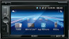
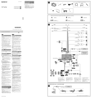
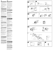
AV Center 4-476-911-62(1) Installation/Connections GB Instalación/Conexiones ES Asegurar la conexión del cable de conexión HDMI/MHL (solo XAV-712BT/612BT) Asegure la conexión entre el cable de conexión HDMI/ MHL y la unidad principal mediante el cierre de gancho y lazo . 1 Envuelva el cierre de gancho y lazo alrededor del cuello de un cable. 2 Tire del cierre de gancho y lazo hacia atrás con firmeza para envolverlo alrededor del otro cable. 3 Una los extremos del cierre de gancho y lazo para asegurar la conexión de los cables. XAV-712BT/XAV-612BT/XAV-602BT ©2013 Sony Corporation Printed in Thailand English Español Cautions ˎˎRun all ground (earth) leads to a common ground (earth) point. ˎˎThis unit is designed for negative ground (earth) 12 V DC operation only. ˎˎDo not disassemble or modify the unit. ˎˎDo not install in locations which interfere with airbag operation. ˎˎDo not get the leads under a screw, or caught in moving parts (e.g. seat railing). ˎˎBefore making connections, turn the car ignition off to avoid short circuits. ˎˎConnect the yellow and red power supply leads only after all other leads have been connected. ˎˎBe sure to insulate any loose unconnected leads with electrical tape for safety. ˎˎDo not press on the LCD when installing the unit. ˎˎInstall the unit with the monitor facing straight forward; do not install it at a slanted angle. Notes on the power supply lead (yellow) ˎˎWhen connecting this unit in combination with other stereo components, the amperage rating of the car circuit to which the unit is connected must be higher than the sum of each component's fuse amperage rating. ˎˎIf no car circuits are rated high enough, connect the unit directly to the battery. Parts list The bracket is attached to the unit before shipping. Before mounting the unit, use the release keys to remove the bracket from the unit. For details, see "Removing the bracket ()" on the reverse side of the sheet. Connection diagram To a common ground (earth) point First connect the black ground (earth) lead, then connect the yellow and red power supply leads. To the power antenna (aerial) control lead or the power supply lead of the antenna (aerial) booster Notes ˎˎIt is not necessary to connect this lead if there is no power antenna (aerial) or antenna (aerial) booster, or with a manually-operated telescopic antenna (aerial). ˎˎIf your car has a built-in FM/AM antenna (aerial) in the rear/ side glass, see "Notes on the control and power supply leads." To AMP REMOTE IN of an optional power amplifier This connection is only for amplifiers. Connecting any other system may damage the unit. To a car's illumination signal Be sure to first connect the black ground (earth) lead to a common ground (earth) point. To the +12 V power terminal which is energized when the ignition switch is set to the accessory position Notes ˎˎIf there is no accessory position, connect to the +12 V power (battery) terminal which is energized at all times. Be sure to first connect the black ground (earth) lead to a common ground (earth) point. ˎˎIf your car has a built-in FM/AM antenna (aerial) in the rear/ side glass, see "Notes on the control and power supply leads." To the +12 V power terminal which is energized at all times Be sure to first connect the black ground (earth) lead to a common ground (earth) point. To the parking brake switch cord The mounting position of the parking brake switch cord depends on your car. For details, see "Connecting the parking brake lead ()" on the reverse side. To an auxiliary device such as a portable media player, game console, etc. (not supplied) Tip You can use an RCA pin cord (not supplied) to connect auxiliary devices. To the +12 V power terminal of the car's rear lamp lead (only when connecting the rear view camera) Notes on the control and power supply leads ˎˎREM OUT lead (blue/white striped) supplies +12 V DC when you turn on the unit. ˎˎIf your car has built-in FM/AM antenna (aerial) in the rear/side glass, connect REM OUT lead (blue/white striped) or the accessory power supply lead (red) to the power terminal of the existing antenna (aerial) booster. For details, consult your dealer. ˎˎA power antenna (aerial) without a relay box cannot be used with this unit. Memory hold connection When the yellow power supply lead is connected, power will always be supplied to the memory circuit even when the ignition switch is turned off. Notes on speaker connection ˎˎBefore connecting the speakers, turn the unit off. ˎˎUse speakers with an impedance of 4 to 8 ohms, and with adequate power handling capacities to avoid damage. ˎˎDo not connect the speaker terminals to the car chassis, or connect the terminals of the right speakers with those of the left speakers. ˎˎDo not connect the ground (earth) lead of this unit to the negative (-) terminal of a speaker. ˎˎDo not attempt to connect the speakers in parallel. ˎˎConnect only passive speakers. Connecting active speakers (with built-in amplifiers) to the speaker terminals may damage the unit. ˎˎTo avoid a malfunction, do not use the built-in speaker leads installed in your car if they feature a common negative (-) lead for the right and left speakers. ˎˎDo not connect the unit's speaker leads to each other. Notes on connection ˎˎIf [Check Audio Output Wiring] appears in the display, make sure the speaker and amplifier are connected correctly. ˎˎTo use the monitor for the rear seats, connect the parking brake switch cord to the ground (earth). Securing the connection of the HDMI/MHL connection cable (XAV-712BT/612BT only) Secure the connection between the HDMI/MHL connection cable and main unit, using the hook and loop fastener . 1 Wrap the hook and loop fastener around the neck of a cable. 2 Pull the hook and loop fastener firmly back around the neck of the other cable. 3 Bring the ends of the hook and loop fastener together to secure the connection of the cables. Precauciones ˎˎConecte todos los cables de conexión a masa a un punto común. ˎˎEsta unidad ha sido diseñada para alimentarse solamente con cc de 12 V de masa negativa. ˎˎNo desmonte ni modifique la unidad. ˎˎNo instale la unidad en lugares en los que interfiera con el funcionamiento del airbag. ˎˎNo coloque los cables debajo de ningún tornillo, ni los aprisione con partes móviles (p. ej. los raíles del asiento). ˎˎAntes de realizar las conexiones, desactive el encendido del automóvil para evitar cortocircuitos. ˎˎConecte los cables de fuente de alimentación amarillo y rojo solamente después de haber conectado los demás. ˎˎPor razones de seguridad, asegúrese de aislar con cinta aislante los cables sueltos que no estén conectados. ˎˎNo presione la pantalla LCD cuando instale la unidad. ˎˎAl instalar la unidad, el monitor debe mirar hacia adelante; no la instale en un ángulo inclinado. Notas sobre el cable de fuente de alimentación (amarillo) ˎˎCuando conecte esta unidad en combinación con otros componentes estéreo, la capacidad nominal del circuito conectado del automóvil debe ser superior a la suma del fusible de cada componente. ˎˎSi no hay circuitos del automóvil con capacidad nominal suficientemente alta, conecte la unidad directamente a la batería. Lista de componentes El soporte se coloca en la unidad antes de ser transportada. Antes de montarla, utilice las llaves de liberación para extraer el soporte . Para obtener más información, consulte "Extracción del soporte ()" en el reverso de esta página. Diagrama de conexiones A un punto de conexión a masa común Conecte primero el cable de conexión a masa negro, y después los cables de fuente de alimentación rojo y amarillo. Al cable de control de la antena motorizada o al cable de fuente de alimentación del amplificador de señal de la antena Notas ˎˎSi no se dispone de antena motorizada ni de amplificador de señal de la antena, o se utiliza una antena telescópica accionada manualmente, no será necesario conectar este cable. ˎˎSi el automóvil tiene una antena FM/AM integrada en el cristal posterior o lateral, consulte las "Notas sobre los cables de control y de fuente de alimentación". A AMP REMOTE IN de un amplificador de potencia opcional Esta conexión es sólo para amplificadores. La conexión de cualquier otro sistema puede dañar la unidad. A una señal de iluminación del automóvil Asegúrese de conectar primero el cable de conexión a masa negro a un punto de conexión a masa común. Al terminal de alimentación de +12 V que recibe energía cuando el interruptor de la llave de encendido se coloca en la posición de accesorio Notas ˎˎSi no hay posición de accesorio, conéctelo al terminal de alimentación (batería) de +12 V que recibe energía sin interrupción. Asegúrese de conectar primero el cable de conexión a masa negro a un punto de conexión a masa común. ˎˎSi el automóvil tiene una antena FM/AM integrada en el cristal posterior o lateral, consulte las "Notas sobre los cables de control y de fuente de alimentación". Al terminal de alimentación de +12 V que recibe energía sin interrupción Asegúrese de conectar primero el cable de conexión a masa negro a un punto de conexión a masa común. Al cable de conmutación del freno de estacionamiento La posición de montaje del cable de conmutación del freno de estacionamiento depende del automóvil. Para obtener detalles, vea la sección "Conexión del cable del freno de estacionamiento ()" del lado reverso. A un dispositivo auxiliar, como, por ejemplo, un reproductor portátil, una consola de videojuegos, etc. (no suministrados) Sugerencia Es posible utilizar el cable con terminales RCA (no suministrado) para conectar dispositivos auxiliares. Al terminal de alimentación de +12 V del cable del indicador posterior del automóvil (únicamente cuando conecte la cámara retrovisora) Notas sobre los cables de control y de fuente de alimentación ˎˎEl cable REM OUT (rayado azul y blanco) suministra cc +12 V al encender la unidad. ˎˎSi el automóvil dispone de una antena de FM/AM incorporada en el cristal trasero o lateral, conecte el cable REM OUT (rayado azul y blanco) o el cable de fuente de alimentación auxiliar (rojo) al terminal de alimentación del amplificador de señal de la antena existente. Para obtener más detalles, consulte a su distribuidor. ˎˎCon esta unidad no es posible utilizar una antena motorizada sin caja de relé. Conexión para protección de la memoria Si conecta el cable de fuente de alimentación amarillo, el circuito de la memoria recibirá siempre alimentación, aunque apague el interruptor de encendido. Notas sobre la conexión de los altavoces ˎˎAntes de conectar los altavoces, desconecte la alimentación de la unidad. ˎˎUtilice altavoces con una impedancia de 4 a 8 Ω con la capacidad de potencia adecuada para evitar que se dañen. ˎˎNo conecte los terminales de altavoz al chasis del automóvil ni conecte los terminales de altavoz derecho con los del izquierdo. ˎˎNo conecte el cable de conexión a masa de esta unidad al terminal negativo (-) del altavoz. ˎˎNo intente conectar los altavoces en paralelo. ˎˎConecte solamente altavoces pasivos. Si conecta altavoces activos (con amplificadores incorporados) a los terminales de altavoz, puede dañar la unidad. ˎˎPara evitar fallas de funcionamiento, no utilice los cables de altavoz integrados instalados en el automóvil si la unidad comparte un cable negativo común (-) para los altavoces derecho e izquierdo. ˎˎNo conecte los cables de altavoz de la unidad entre sí. Notas sobre la conexión ˎˎSi en la pantalla aparece [Verifique el cableado de salida audio], verifique que el altavoz y el amplificador estén conectados correctamente. ˎˎSi va a utilizar el monitor para los asientos posteriores, conecte el cable de conmutación del freno de estacionamiento a masa. × 2 × 6 a b XAV-712BT/612BT only / solo XAV-712BT/612BT Equipment used in illustrations (not supplied) / Equipo utilizado en las ilustraciones (no suministrado) Front speaker Altavoz frontal Rear speaker Altavoz posterior Power amplifier Amplificador de potencia Subwoofer Altavoz potenciador de graves Rear view camera Cámara retrovisora Monitor Monitor GND Black Negro Red Rojo REM OUT Max. supply current: 0.4 A Corriente máx. de alimentación: 0,4 A ILLUMINATION Blue/white striped Con rayas azules/blancas Orange/white striped Con rayas naranjas/blancas Yellow Amarillo Light green Verde claro *2 *9 From car antenna (aerial) Desde la antena del automóvil *1 Fuse (10 A) Fusible (10 A) *2 ACC BATTERY White Blanco White/black striped Con rayas blancas/negras Gray Gris Gray/black striped Con rayas grises/negras Green Verde Green/black striped Con rayas verdes/negras Purple Morado Purple/black striped Con rayas moradas/negras PARKING BRAKE Left Izquierdo Right Derecho *10 Left Izquierdo Right Derecho or *3 / o *3 Smartphone Teléfono inteligente *8 HIGH CHARGE *6 Smartphone*7, USB device Teléfono inteligente*7, dispositivo USB *2 *2 *2 *2 *1 For details on installing the microphone, see "Installing the microphone ()" on the reverse side. *2 RCA pin cord (not supplied) *3 HDMI connection cable or MHL connection cable (supplied) (XAV-712BT/612BT only) *4 The sound is output from this terminal only when ZONE × ZONE is activated. This terminal outputs a fixed level regardless of the volume control of the unit. *5 A separate adaptor may be required. *6 The USB rear cable labeled "HIGH CHARGE" is recommended to use for recharging the battery of a connected device. *7 To connect a smartphone to the main unit, an appropriate cable (not supplied) is required. *8 The USB rear cable without "HIGH CHARGE" label (XAV-712BT only) *9 The HDMI in/MHL in port (XAV-712BT/612BT only) *10Speaker impedance: 4 - 8 ohms × 4 *1 Para obtener detalles sobre la instalación del micrófono, consulte "Instalación del micrófono ()" al reverso. *2 Cable con terminales RCA (no suministrado) *3 Cable de conexión HDMI o MHL (suministrados) (solo XAV-712BT/612BT) *4 El sonido se emitirá a través de este terminal sólo cuando esté activado ZONE × ZONE. Este terminal emite a un nivel fijo independientemente del control de volumen de la unidad. *5 Puede requerirse un adaptador independiente. *6 Se recomienda utilizar el cable posterior de USB denominado "HIGH CHARGE" para recargar la batería de un dispositivo conectado. *7 Para conectar un teléfono inteligente a la unidad principal, es necesario utilizar un cable adecuado (no suministrado). *8 El cable USB posterior sin la etiqueta "HIGH CHARGE" (solo XAV-712BT) *9 Entrada HDMI/MHL en el puerto (solo XAV-712BT/612BT) *10Impedancia del altavoz: 4 - 8 Ω × 4 XAV-712BT/612BT only / solo XAV-712BT/612BT or *1 / o *1 Smartphone Teléfono inteligente *1 HDMI connection cable or MHL connection cable (supplied) (XAV-712BT/612BT only) *1 Cable de conexión HDMI o MHL (suministrados) (solo XAV-712BT/612BT)
-
 1
1 -
 2
2
 |
 |