Sony XAV-602BT Installation Guide 1 - Page 2
XAV-712BT, XAV-612BT/602BT, XAV-612BT/602BT only / solo XAV-612BT/602BT, XAV-712BT only/ solo XAV-
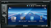 |
View all Sony XAV-602BT manuals
Add to My Manuals
Save this manual to your list of manuals |
Page 2 highlights
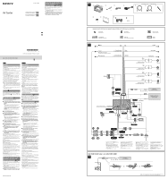
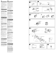
English Español Precautions ˎˎChoose the installation location carefully so that the unit will not interfere with normal driving operations. ˎˎAvoid installing the unit in areas subject to dust, dirt, excessive vibration, or high temperature, such as in direct sunlight or near heater ducts. ˎˎUse only the supplied mounting hardware for a safe and secure installation. ˎˎTo move the front panel smoothly, to insert/eject a disc easily, and especially to drive safely, keep an adequate distance between the front panel and the shift lever. The necessary distance differs, depending on the shift lever position of your car. Before installing the unit, choose the installation location carefully so that you can drive safely. (For XAV-712BT, see fig. .) Mounting angle adjustment Adjust the mounting angle to less than 45°. Precauciones ˎˎElija cuidadosamente el lugar de montaje de forma que la unidad no interfiera con las funciones normales de conducción. ˎˎEvite instalar la unidad donde pueda quedar sometida a polvo, suciedad, vibraciones excesivas o altas temperaturas como, por ejemplo, a la luz solar directa o cerca de conductos de calefacción. ˎˎPara realizar una instalación segura y firme, utilice solamente elementos de instalación suministrados. ˎˎPara mover el panel frontal con suavidad, insertar/ extraer discos fácilmente y, sobre todo, para conducir con seguridad, es necesario mantener una distancia adecuada entre el panel frontal y la palanca de cambios. La distancia necesaria varía en función de la posición de la palanca de cambios de su automóvil. Antes de instalar la unidad, elija cuidadosamente el lugar de instalación para que pueda conducir con seguridad. (Para XAV-712BT, ver la fig. .) About illustrations XAV-602BT is the model used for illustration purposes, unless otherwise noted. Connecting the parking brake lead Be sure to connect the parking brake lead (light green) of the power supply connection cable to the parking brake switch cord. Installing the microphone To capture your voice during handsfree calling, you need to install the microphone . Cautions ˎˎKeep the microphone away from extremely high temperatures and humidity. ˎˎIt is extremely dangerous if the cord becomes wound around the steering column or gearstick. Be sure to keep it and other parts from obstructing your driving. ˎˎIf airbags or any other shock-absorbing equipment is in your car, contact the store where you purchased this unit, or the car dealer, before installation. Notes ˎˎBefore attaching the double-sided tape b , clean the surface of the dashboard with a dry cloth. ˎˎAdjust the microphone angle to the proper position. How to detach and attach the front panel (XAV-612BT/602BT only) Before installing the unit, detach the front panel. Ajuste del ángulo de montaje Ajuste el ángulo de montaje a menos de 45°. Acerca de las ilustraciones XAV-602BT es el modelo que se utiliza para las ilustraciones, a menos que se indique lo contrario. Conexión del cable del freno de estacionamiento Asegúrese de conectar el cable del freno de estacionamiento (verde claro) del cable de conexión de la fuente de alimentación al cable de conmutación del freno de estacionamiento. Instalación del micrófono Para capturar la voz durante llamadas con manos libres, debe instalar el micrófono . Precauciones ˎˎMantenga el micrófono alejado de lugares con humedad y temperaturas muy altas. ˎˎQue el cable se enrolle alrededor del volante o de la palanca de cambios es extremadamente peligroso. Asegúrese de impedir que el cable y otros componentes obstruyan la conducción. ˎˎSi el vehículo dispone de airbags u otros dispositivos de amortiguación de impactos, póngase en contacto con el establecimiento donde ha adquirido esta unidad o con el concesionario de automóviles antes de llevar a cabo la instalación. Notas ˎˎAntes de colocar la cinta adhesiva de doble cara b , limpie la superficie del tablero con un paño seco. ˎˎAjuste el ángulo del micrófono en la posición adecuada. -A To detach Before detaching the front panel, press and hold OFF for more than 2 seconds to turn off the unit. Press , and then hold the left side of the front panel and pull it open to the right. Tip If you also lift the left side of the front panel slightly , the front panel comes out easily. -B To attach Place the recesses of the front panel onto the pegs on the unit, then lightly push the left side in. Removing the bracket Before installing the unit, remove the bracket from the unit. Keep the release keys for future use as they are also necessary if you remove the unit from your car. Caution Handle the bracket carefully to avoid injuring your fingers. 1 Insert the release keys into the catches between the unit and the bracket at the same time until they click. 2 Pull down the bracket , then pull up the unit to separate them. Note The form of the frame and location of the catch may differ depending on the model. Mounting the unit -A Mounting the unit with the supplied bracket 1 Before installing, make sure that the catches on both sides of the bracket are bent inwards 3.5 mm (5/32 in). 2 Position the supplied bracket inside the dashboard. 3 Bend the claws outward for a tight fit. 4 Mount the unit onto the supplied bracket . Note If the catches are straight or bent outwards, the unit will not be installed securely and may spring out. -B Mounting the unit in a Japanese car You may be able to install this unit in some makes of Japanese cars without the supplied bracket. If you cannot, consult your Sony dealer. When mounting this unit to the preinstalled brackets of your car, use the supplied screws in the appropriate screw holes, based on your car: T for TOYOTA, M for MITSUBISHI and N for NISSAN. Notes ˎˎTo avoid a malfunction, install only with the supplied screws . ˎˎDo not apply excessive force to the buttons of the unit. ˎˎDo not press on the LCD. ˎˎBefore mounting, make sure there is nothing on the top of the unit. Warning if your car's ignition has no ACC position Be sure to set the Auto OFF function. For details, refer to the supplied "Operating Instructions." The unit will shut off completely and automatically in the set time when no source is selected, which prevents battery drainage. If the Auto OFF function has not been set, press and hold OFF until the display disappears each time you turn the ignition off. Reset button When the installation and connections are completed, be sure to press the reset button, which is located behind the front panel, with a ballpoint pen, etc. Fuse replacement When replacing the fuse, be sure to use one matching the amperage rating stated on the original fuse. If the fuse blows, check the power connection and replace the fuse. If the fuse blows again after replacement, there may be an internal malfunction. In such a case, consult your nearest Sony dealer. Forma de extraer e instalar el panel frontal (solo XAV612BT/602BT) Antes de instalar la unidad, extraiga el panel frontal. -A Para extraerlo Antes de extraer el panel frontal, mantenga presionado OFF durante más de 2 segundos para desactivar la unidad. Presione , y luego mantenga apretado el lado izquierdo del panel frontal y tire hacia la derecha para abrirlo. Consejo Si también levanta ligeramente el lado izquierdo del panel frontal , el panel frontal saldrá fácilmente. -B Para instalarlo Coloque los orificios del panel frontal en las clavijas de la unidad, luego presione suavemente el lado izquierdo. Extracción del soporte Antes de instalar la unidad, extraiga el soporte de la unidad. Conserve las llaves de liberación para utilizarlas en el futuro, ya que también las necesitará si retira la unidad del automóvil. Precaución Tenga mucho cuidado al manipular el soporte para evitar posibles lesiones en los dedos. 1 Inserte las llaves de liberación en los enganches entre la unidad y el soporte al mismo tiempo hasta que encajen. 2 Presione el soporte y, a continuación, levante la unidad para separar ambos elementos. Nota La forma del marco y la ubicación de los enganches pueden ser diferentes según el modelo. Montaje de la unidad -A Montaje de la unidad con el soporte suministrado 1 Antes de instalar la unidad, compruebe que los enganches de ambos lados del soporte estén doblados hacia adentro 3,5 mm. 2 Coloque el soporte suministrado dentro del salpicadero. 3 Doble los ganchos hacia fuera para conseguir una fijación segura. 4 Monte la unidad en el soporte suministrado . Nota Si los enganches están derechos o doblados hacia afuera, la unidad no se instalará correctamente y puede desprenderse. -B Montaje de la unidad en un automóvil japonés Es posible que pueda instalar la unidad en algunos automóviles japoneses sin el soporte suministrado. En caso de que no pudiera, consulte al distribuidor Sony más cercano. Cuando monte la unidad en los soportes preinstalados de su automóvil, utilice los tornillos suministrados en los orificios para tornillos correspondientes en función de su automóvil: T para TOYOTA, M para MITSUBISHI y N para NISSAN. Notas ˎˎPara evitar que se produzcan fallas de funcionamiento, realice la instalación solamente con los tornillos suministrados . ˎˎNo ejerza excesiva fuerza sobre los botones de la unidad. ˎˎNo presione la pantalla LCD. ˎˎAsegúrese de que no haya ningún objeto encima de la unidad antes de montarla. Advertencia: si el encendido del automóvil no dispone de una posición ACC Asegúrese de ajustar la función Auto DESACTIVAR. Para obtener más información, consulte el "Manual de instrucciones" suministrado. La unidad se apagará completa y automáticamente en el tiempo establecido si no se selecciona ninguna fuente, lo cual evita que se desgaste la batería. Si no ha ajustado la función Auto DESACTIVAR, mantenga presionado OFF cada vez que apague el interruptor de encendido, hasta que la pantalla desaparezca. Botón de reinicio Una vez finalizadas la instalación y las conexiones, asegúrese de presionar el botón de reinicio, que está ubicado detrás del panel frontal, con un bolígrafo, etc. Sustitución del fusible Al sustituir el fusible, asegúrese de utilizar uno cuyo amperaje coincida con el especificado en el original. Si el fusible se funde, verifique la conexión de alimentación y sustitúyalo. Si el fusible vuelve a fundirse después de sustituirlo, es posible que exista alguna falla de funcionamiento interno. En tal caso, consulte con el distribuidor Sony más cercano. XAV-712BT only/ solo XAV-712BT Shift lever Palanca de cambios 87 mm (3 1/2 in) 87 mm Foot brake type Tipo de freno de pedal Hand brake type Tipo de freno manual Parking brake switch cord Cable de conmutación del freno de estacionamiento Parking brake switch cord Cable de conmutación del freno de estacionamiento Installing on the sun visor / Instalación en la visera a Installing on the dashboard / Instalación en el salpicadero a Clips (not supplied) Clips (no suministrados) XAV-612BT/602BT only / solo XAV-612BT/602BT A B Clip (not supplied) Clip (no suministrado) b Face the hook inwards. El gancho debe encontrarse en la parte interior. Catch Enganche A Larger than 182 mm (7 1/4 in) Superior a 182 mm B Larger than 111 mm (4 3/8 in) Superior a 111 mm Catch Enganche Size: 5 × max. 8 mm (7/32 × max. 5/16 in) Tamaño: 5 × 8 mm máx. To the dashboard/center console Al tablero o consola central Bracket Soporte Dashboard Tablero Claws Uñas Location of screw holes Ubicación de los orificios para los tornillos T: TOYOTA M: MITSUBISHI N: NISSAN Parts supplied with your car Partes suministradas con el automóvil Bracket Soporte Size: 5 × max. 8 mm (7/32 × max. 5/16 in) Tamaño: 5 × 8 mm máx. XAV-712BT XAV-612BT/602BT Fuse (10 A) Fusible (10 A)
-
 1
1 -
 2
2
 |
 |
