Sony XCLU100 Operating Instructions
Sony XCLU100 Manual
 |
View all Sony XCLU100 manuals
Add to My Manuals
Save this manual to your list of manuals |
Sony XCLU100 manual content summary:
- Sony XCLU100 | Operating Instructions - Page 1
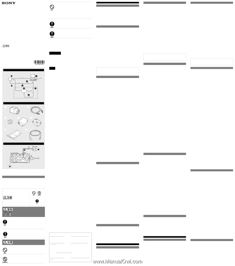
authorized Sony service Camera Link feature. You can use either a board that supports Instruction Manual. C-mount lens Camera cable (e.g. CCXC-12P05N) TRIG generator, Image processor To DC IN connector To CAMERA connector To AC IN connector To AC power source 한국어 A DIGITAL - Sony XCLU100 | Operating Instructions - Page 2
10 V 에서 13 V 까지: DIGITAL IF 2.2 W 0 C 에서 40 C 까지 -5 C 에서 +45 C 까지 -30 C 에서 +60 C 까지 20% 에서 80 20% 에서 95 10 G(20 Hz 에서 200 Hz 까지) 70 G 29 × 29 × 30 mm(1 3/16× 1 3/16 × 1 3/16 55 g (1.9 oz 1 1) SONY About the Technical Manual The Operating Instructions describe the
-
 1
1 -
 2
2
 |
 |
A
B
C
安全のために
ソニー製品は安全に充分に配慮して設計されています。しかし、電気製品はまちがった
使いかたをすると、火災や感電などにより死亡や大けがなど人身事故につながることが
あり、危険です。事故を防ぐために次のことを必ずお守りください。
安全のための注意事項を守る。
ˎ
故障したり破損したら使わずに、ソニーのサービス窓口に相談する。
ˎ
警告表示の意味
この取扱説明書および製品では、次のような表示を
しています。表示の内容をよく理解してから本文を
お読みください。
この表示の注意事項を守らないと、
火災
やその他
の事故により
けが
をしたり周辺の物品に
損害
を
与えたりすることがあります。
行為を禁止する記号
行為を指示する記号
下記の注意を守らないと、
火災
や
感電
、
落下
によ
り
死亡
や
大けが
につながることがあります。
設置は確実に
設置については、必ずお買い上げ店または、巻末に記載してあるお問い合わ
せ窓口にご相談ください。
設置は、本機と取り付け金具を含む重量に充分耐えられる強度があることを
お確かめのうえ確実に取り付けてください。充分な強度がないと、落下して、
大けがの原因となります。
また、
1
年に一度は、取り付けがゆるんでいないことを点検してください。
レンズは確実に取り付ける
レンズはネジ部をしっかり締めて取り付けてください。取り付けかたがゆ
るいと、レンズがはずれてけがの原因となることがあります。
また、
1
年に一度は取り付けがゆるんでいないことを点検してください。
下記の注意事項を守らないと、
けが
をしたり周辺の
物品に
損害
を与えることがあります。
内部に水や異物を入れない
水や異物が入ると、火災の原因となります。
万一、水や異物が入ったときは、すぐに本機が接続されている電源供給機器
の電源を切り、
DC
電源ケーブルや接続ケーブルを抜いて、ソニーのサービ
ス窓口にご相談ください。
分解しない、改造しない
分解や改造をすると、火災やけがの原因となります。
点検および修理は、ソニーのサービス窓口にご依頼ください。
カメラケーブルを傷つけない
カメラケーブルを傷つけると、火災や故障の原因となることがあります。次
の項目をお守りください。
設置時に、製品と壁やラック、棚などの間に、はさみ込まない。
ˎ
カメラケーブルを加工したり、傷つけたりしない。
ˎ
重いものをのせたり、引っ張ったりしない。
ˎ
熱器具に近づけたり、加熱したりしない。
ˎ
カメラケーブルを抜くときは、必ずプラグを持って抜く。
ˎ
芯線の露出や断線などでカメラケーブルが傷んだら、お買い上げ店に交換
をご依頼ください。そのまま使用すると、火災の原因となります。
指定された電源を使う
この取扱説明書に記されている電源供給機器(カメラアダプターなど)でお
使いください。規定外の電源でのご使用は、火災の原因となることがありま
す。
指定されたカメラケーブル、接続ケーブルを使う
この取扱説明書に記されているカメラケーブル、接続ケーブルを使わない
と、火災や故障の原因となることがあります。
Owner’s Record
The model and serial numbers are located on the bottom.
Record the serial number in the space provided below. Refer
to these numbers whenever you call upon your Sony dealer
regarding this product.
Model No. _____________
Serial No. ______________
WARNING
To reduce the risk of fire or electric shock, do not
expose this apparatus to rain or moisture.
To avoid electrical shock, do not open the cabinet.
Refer servicing to qualified personnel only.
경고
화재나 감전 위험을 방지하려면 장치가 물기나
습기에 노출되지 않도록 하십시오.
감전 위험이 있으므로 본체를 열지 마십시오. 자격
있는 전문 정비 요원만 서비스를 실시해야 합니다.
IMPORTANT
The nameplate is located on the bottom.
중요
명판은 바닥에 있습니다.
For the customers in the U.S.A.
This equipment has been tested and found to comply with the limits for a Class A
digital device, pursuant to part 15 of the FCC Rules. These limits are designed to
provide reasonable protection against harmful interference when the equipment
is operated in a commercial environment. This equipment generates, uses, and can
radiate radio frequency energy and, if not installed and used in accordance with
the instruction manual, may cause harmful interference to radio communications.
Operation of this equipment in a residential area is likely to cause harmful interference
in which case the user will be required to correct the interference at his own expense.
You are cautioned that any changes or modifications not expressly approved in this
manual could void your authority to operate this equipment.
All interface cables used to connect peripherals must be shielded in order to comply
with the limits for a digital device pursuant to Subpart B of part 15 of FCC Rules.
This device complies with part 15 of the FCC Rules. Operation is subject to the
following two conditions: (1) This device may not cause harmful interference, and (2)
this device must accept any interference received, including interference that may
cause undesired operation.
For the customers in Canada
This Class A digital apparatus complies with Canadian ICES-003.
Pour les utilisateurs au Canada
Cet appareil numérique de la classe A est conforme à la norme NMB-003 du Canada.
For the customers in Europe, Australia and New Zealand
WARNING
This is a Class A product. In a domestic environment, this product may cause radio
interference in which case the user may be required to take adequate measures.
In the case that interference should occur, consult your nearest authorized Sony
service facility.
Pour les clients en Europe, Australie et Nouvelle-Zélande
AVERTISSEMENT
Il s’agit d’un produit de Classe A. Dans un environnement domestique, cet appareil
peut provoquer des interférences radio, dans ce cas l’utilisateur peut être amené à
prendre des mesures appropriées.
Si des interférences se produisent, contactez votre service après-vente agréé Sony.
Für Kunden in Europa, Australien und Neuseeland
WARNUNG
Dies ist eine Einrichtung, welche die Funk-Entstörung nach Klasse A besitzt. Diese
Einrichtung kann im Wohnbereich Funkstörungen verursachen; in diesem Fall kann
vom Betreiber verlangt werden, angemessene Maßnahmen durchzuführen und dafür
aufzukommen.
Sollten Funkstörungen auftreten, wenden Sie sich bitte an den nächsten autorisierten
Sony-Kundendienst.
A급 기기(업무용 방송통신기자재)
이 기기는 업무용(A급) 전자파적합기기로서 판매자 또는 사용자는 이 점을
주의하시기 바라며, 가정외의 지역에서 사용하는 것을 목적으로 합니다.
For the customers in Europe
The manufacturer of this product is Sony Corporation, 1-7-1 Konan, Minato-ku, Tokyo,
Japan.
The Authorized Representative for EMC and product safety is Sony Deutschland GmbH,
Hedelfinger Strasse 61, 70327 Stuttgart, Germany. For any service or guarantee matters
please refer to the addresses given in separate service or guarantee documents.
This apparatus shall not be used in the residential area.
Pour les clients en Europe
Le fabricant de ce produit est Sony Corporation, 1-7-1 Konan, Minato-ku, Tokyo, Japon.
Le représentant autorisé pour EMC et la sécurité des produits est Sony Deutschland
GmbH, Hedelfinger Strasse 61, 70327 Stuttgart, Allemagne. Pour toute question
concernant le service ou la garantie, veuillez consulter les adresses indiquées dans les
documents de service ou de garantie séparés.
Ne pas utiliser cet appareil dans une zone résidentielle.
Für Kunden in Europa
Der Hersteller dieses Produkts ist Sony Corporation, 1-7-1 Konan, Minato-ku, Tokyo,
Japan.
Der autorisierte Repräsentant für EMV und Produktsicherheit ist Sony Deutschland
GmbH, Hedelfinger Strasse 61, 70327 Stuttgart, Deutschland. Bei jeglichen
Angelegenheiten in Bezug auf Kundendienst oder Garantie wenden Sie sich bitte an die
in den separaten Kundendienst- oder Garantiedokumenten aufgeführten Anschriften.
Dieser Apparat darf nicht im Wohnbereich verwendet werden.
모델명: XCL-U100
승인된 상표명: Sony EMCS Corp.
제조사/제조 국가: Sony EMCS Corp. (일본)
인증신청인 식별부호: MKM
A/S 센터
공신테크노소닉 주식회사
서울특별시 영등포구 여의도동 23-8 동양증권빌딩 13층
전화: 02-785-3441
다이트론코리아 주식회사
서울시 구로구 구로동 197-28 이앤씨벤처드림타워 6차 703호
전화: 02-6910-3336
팩스: 02-6910-3399
Note: This camera is not intended for use in security applications in the meaning of
the European standard series EN 50132 (Alarm systems - CCTV surveillance systems for
use in security applications).
For the customers in the U.S.A.
SONY LIMITED WARRANTY
- Please visit http://www.sony.com/psa/warranty
for important information and complete terms and conditions of Sony’s limited
warranty applicable to this product.
For the customers in Canada
SONY LIMITED WARRANTY
- Please visit http://www.sonybiz.ca/solutions/
Support.do for important information and complete terms and conditions of
Sony’s limited warranty applicable to this product.
For the customers in Europe
Sony Professional Solutions Europe - Standard Warranty and Exceptions on
Standard Warranty.
Please visit http://www.pro.sony.eu/warranty for important information and
complete terms and conditions.
For the customers in Korea
SONY LIMITED WARRANTY
- Please visit http://bpeng.sony.co.kr/handler/BPAS-
Start for important information and complete terms and conditions of Sony’s
limited warranty applicable to this product.
Notes on Operation
Power supply
You can supply power to the XCL-U100 using the following methods.
Using the DIGITAL IF (interface) connector
The XCL-U100 supports the PoCL (Power over Camera Link) standard. By connecting
a PoCL-compatible camera link cable to a PoCL-compatible camera module interface
board, you can power, control, and output images from the camera using a single
cable.
Using the DC IN connector
You can supply power via the DC IN connector using the power adapter.
Use DC-700/700CE which is the stable power source free from ripple or noise.
When both the DIGITAL IF and DC IN connectors are used, the power supply from the
DC IN connector is given priority.
Foreign bodies
Be careful not to spill liquids, or drop any flammable or metal objects in the camera
body.
Locations for operation and storage
Avoid operation or storage in the following places.
Extremely hot or cold locations. Recommended temperature range is 0 °C to
ˎ
40 °C (32 °F to 104 °F)
Locations subject to strong vibration or shock.
ˎ
Near generators of strong electromagnetic radiation such as TV or radio
ˎ
transmitters.
Care
Use a blower to remove dust from the surface of the lens or optical filter. Clean the
exterior with a soft, dry cloth.
If the camera is very grimy, apply a cloth soaked in a mild detergent then wipe with
a dry cloth. Do not apply organic solvents such as alcohol or benzine which may
damage the finish.
Note on laser beams
Laser beams may damage a CCD. You are cautioned that the surface of a CCD
should not be exposed to laser beam radiation in an environment where a laser
beam device is used.
Overview
Before operating the unit, please read this manual thoroughly and retain for future
reference.
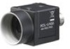
The XCL-U100 is a monochrome digital video camera module. This camera module
outputs digital images utilizing LVDS via the DIGITAL IF connector.
DIGITAL IF connector
Equipped with a Camera Link standard mini connector. The
XCL-U100 can output a digital image at 15 frames per second.
High image quality
The XCL-U100 has a progressive scan CCD of 2,000,000 pixels. Both cameras produce
high-resolution images. By adopting square pixels, images can be processed using the
original aspect ratio without a converting procedure.
Various mode settings
Sending a command from the host device allows the following mode settings.
Gain
ˎ
Read mode: normal /binning
ˎ
Partial scan
ˎ
Shutter: Normal/Trigger shutter
ˎ
Shutter speed
ˎ
Gamma
ˎ
Switching an output Bit Length
ˎ
Outline detection (with 3 × 3 filter)
ˎ
Binarization
ˎ
Electronic shutter function
Shutter speed can be selected from variety of available speeds.
External trigger shutter function (2 sec. to 1/10,000 sec.)
You can obtain a freeze picture by inputting an external trigger. This function is useful
to shoot a fast-moving object clearly.
Partial scan
The camera module can limit the number of effective video output lines to achieve
high frame rates, enabling high-speed image processing.
Body fixing
The screw holes to install the camera module are located under the front panel (the
CCD reference plane). Installing the camera module on the front panel minimizes
deviation of the optical axis.
Gamma
You can switch to OFF or ON. When you switch to ON, you can select from various
modes, and draw not only the default gamma line but also an original gamma line.
Switching an Output Bit Length
You can select 8 bit output, 10 bit output, or 12 bit output.
Binning
By “binning” two pixels that align vertically, you can acquire a frame rate twice as high
as that in the normal mode.
3 × 3 filter
You can configure the 3 × 3 filter manually.
Six different table presets are also available.
Outline detection detects an outline from a picture and outputs an image made of the
outline only.
Binarization
Outputs an binarized image. Sensitivity can be changed.
System Components
B
The Video Camera Module XCL-U100 system comprises the following optional
products (available separately).
Video Camera Module
This is a small-size, high-resolution, video camera module using a progressive scan
CCD image sensor.
CCXC-12P02N (2 m, 6.6 ft)/05N (5 m, 16.4 ft)/10N (10 m, 32.8 ft)/
25N (25 m, 82 ft) camera cable
This is attached to the DC IN connector of the camera module and is used for power
supply and exchange of trigger signals.
C-mount lens
Use a high-resolution lens.
DC-700/700CE camera adaptor
This is connected to the camera module to enable power supply from ordinary AC
power source.
VCT-333I tripod adaptor
This attaches to the bottom of the camera module to fix the camera module to a
tripod.
Camera module interface board
Install the board in a PCI bus slot in devices such as a computer. Select a commercially
available interface board compatible with the Camera Link feature. You can use either
a board that supports PoCL, or one that does not.
In the board corresponding to PCI 32 bit, the frame rate may become low according
to lack of processing capacity. When you want to make this product output 15 frames
per second, use a board corresponding to more than PCI 64 bit (PCI-X).
Performance may also be dependent on the host device (e.g., Computer), so consult
the dealer if images are not displayed properly.
Camera Link cable
This cable connects to the DIGITAL IF connector on the rear panel of the camera
module. Image/control signals are transmitted via this cable.
If there is support for PoCL, power is also supplied at the same time.
If you use a camera module interface board with support for PoCL, be sure to use a
camera link cable with support for PoCL. Select a proper cable as the maximum usable
length of a cable differs due to the attribute of each cable.
Spotted noise may appear in a specific brightness in the window according to the
attribute of the cable. If this noise is an obstacle, shorten the cable.
Connection Example
C
Connecting DC-700/700CE (not supplied)
Connect the camera module to the power via the camera adaptor DC-700/700CE.
For details on the camera adaptor DC-700/700CE, see the DC-700/700CE Instruction
Manual.
C-mount lens
To DC IN connector
Camera cable (e.g. CCXC-12P05N)
To CAMERA connector
TRIG generator, Image processor
To AC IN connector
To AC power source
한국어
카메라를 설치할 때
A
카메라를 다양한 주변 장치와 함께 설치할 경우 주변 장치의 접지 전위가 서로
다르면 한 장치만 접지하십시오. 접지 전위에 차이가 있으면 카메라가 손상될 수
있습니다.
DIGITAL IF 커넥터
DC IN 커넥터
호스트 장치(예: 컴퓨터)
비정상적인 전력
접지 전위차
전원 공급 장치 (DC-700/700CE)
호스트 장치(예: 컴퓨터) 내의 카메라 모듈 인터페이스 보드에서 PoCL(Power over Camera
ˈ
Link)을 지원하는 경우 점선 내의 항목이 연결되지 않은 경우에도 카메라를 작동시킬 수
있습니다.
日本語
カメラ設置上のご注意
A
カメラ設置の際は、周辺機器を含めてカメラに接続されている各機器間で接地電位の
差が生じないようにしてください。接地電位差により故障の原因となる場合がありま
す。設置の都合により電位差を生ずる場合は、機器の内いずれか
1
つの機器だけを接地
するようにしてください。
DIGITAL IF
端子
DC IN
端子
ホスト機器(コンピューターなど)
異常電流
接地電位差
電源(
DC-700
)
ホスト機器(コンピューターなど)内のカメラ用画像入力ボードが
PoCL
(
Power over Camera
ˈ
Link
)対応の場合は、点線内が未接続でもカメラは動作可能です。
使用上のご注意
電源について
XCL-U100
には、次の方法で電源を供給できます。
DIGITAL IF
端子から供給する
XCL-U100
は、カメラリンク
PoCL
規格を採用していますので、カメラリンク
PoCL
規格に
適合したカメラリンクケーブルとカメラ用画像入力ボードを使用することにより、
1
本
のカメラリンクケーブルで、電源の供給とカメラコントロール/映像出力が可能です。
DC IN
端子から供給する
電源アダプターを使用して、
DC IN
端子から電源を供給します。
電源には、リップルやノイズのない安定した電源である
DC-700
をお使いください。
カメラに対して、
DIGITAL IF
端子と
DC IN
端子の両方から電源が供給された場合は、
DC IN
端子からの電源供給が優先されます。
使用・保管場所
次のような場所での使用および保管はお避けください。
極端に暑い所や寒い所。適正使用温度は
0
℃~
40
℃です。
ˎ
激しい振動や衝撃のある所。
ˎ
強力な電波を発生するテレビ、ラジオの送信所の近く。
ˎ
お手入れ
レンズや光学フィルターの表面に付着したごみやほこりは、ブロアーで払ってくださ
い。外装の汚れは、乾いた柔らかい布でふきとります。ひどい汚れは、中性洗剤溶液を
少し含ませた布でふきとった後、からぶきします。アルコール、ベンジンなどは、変質し
たり塗料がはげることがありますので、使用しないでください。
レーザービームについてのご注意
レーザービームは
CCD
に損傷を与えることがあります。レーザービームを使用した
撮影環境では、
CCD
表面にレーザービームが照射されないように充分注意してくだ
さい。
概要
XCL-U100
は
DIGITAL IF
端子により
LVDS
信号による映像出力を実現した白黒デジタル
ビデオカメラモジュールです。
DIGITAL IF
端子
カメラリンク規格のミニコネクターを採用。毎秒
15
フレームの画像のデジタル出力が
可能。
高画質
200
万画素の高画素
CCD
を採用。きめ細かな画像を再現します。また正方画素
CCD
の
採用により、画像処理時のアスペクト比変換は不要です。
多様なモード設定
ホスト機器からのコマンド送信により、以下のモード設定が可能です。
ゲイン
ˎ
読み出しモード
:
ノーマル/ビニング
ˎ
部分読み出し機能
ˎ
シャッター機能
:
ノーマル/トリガーシャッター
ˎ
シャッタースピード
ˎ
ガンマ
ˎ
出力ビット長切り替え
ˎ
輪郭検出(
3
×
3
フィルターにて)
ˎ
2
値化
ˎ
電子シャッター
豊富なシャッタースピードの中から、撮影条件に合った速度が選べます。
外部トリガーシャッター機能(
2
秒~
1/10,000
秒)
トリガーを入力することにより、
1
枚の静止画が得られます。高速で移動する物体を
正確にとらえます。
部分読み出し機能
有効な映像出力ライン数を限定することにより、高速な画像処理に適したフレーム
レートの高い映像出力が得られます。
筐体固定
筐体固定用のネジ穴が
CCD
の基準面が含まれているフロントパネルの下部にあります。
ここでカメラモジュールを固定すれば、光軸のずれを最小限にとどめることができます。
ガンマ
オフ/オンの切り替えができます。
オンの場合は、多彩なモードの中から選択でき、既定のガンマ曲線だけでなく、任意の
ガンマ曲線を作成することもできます。
出力ビット長切り替え
8 bit
出力/
10 bit
出力/
12 bit
出力から選択できます。
ビニング機能
垂直方向の
2
画素を混合した映像信号がノーマル比で
2
倍のフレームレートで得られます。
3
×
3
フィルター
任意で
3
×
3
フィルターの設定が可能です。
6
種類のテーブルがプリセットされています。
輪郭検出では、映像の中から輪郭を検出し、輪郭のみの画像を出力します。
2
値化
2
値化処理をした映像出力が得られます。しきい値は変更可能です。
構成
B
ビデオカメラモジュール
XCL-U100
を中心としたシステムの構成品目は、次のとおりで
す。
(いずれも別売りです。)
ビデオカメラモジュール
CCD
を用いた、小型、高解像度のカメラです。
カメラケーブル
CCXC-12P02N
(
2 m
)
/05N
(
5 m
)
/10N
(
10 m
)
/25N
(
25 m
)
カメラモジュール後面の
DC IN
端子に接続し、電力の供給やトリガー信号の授受を行い
ます。
C
マウントレンズ
高解像度対応レンズをお使いください。
カメラアダプター
DC-700
AC
電源から電力を供給する場合に、カメラモジュールに接続して使用します。
三脚アダプター
VCT-333I
三脚を使ってカメラモジュールを固定するとき、このアダプターをカメラモジュール
の底部に取り付けます。
カメラ用画像入力ボード
ホスト機器(コンピューターなど)の
PCI
バススロットに挿入します。カメラリンク対
応のボード(市販品)をご使用ください。
PoCL
対応/非対応のいずれのボードも使用で
きます。
ただし、
PCI 32 bit
対応のボードでは、処理能力不足によりフレームレートが低くなる
場合があります。毎秒
15
フレームの画像を出力させたい場合は、
PCI 64 bit
(
PCI-X
)
以上対応のボードをお使いください。
なお、ホスト機器(コンピューターなど)の性能に依存する場合もありますので、画像が
正しく表示されないときは、お買い上げ店にご相談ください。
カメラリンクケーブル
リアパネルの
DIGITAL IF
端子に接続し、映像信号の送出や制御信号の授受を行います。
PoCL
対応の場合は、同時に電源供給も行います。
PoCL
対応のカメラ用画像入力ボードを使用する場合は、必ず
PoCL
対応のカメラリン
クケーブルをお使いください。
最大使用可能ケーブル長はケーブルの特性により異なりますので、ケーブルを選定す
る際はご注意ください。
なお、ケーブルの特性によっては、画面の特定輝度の部分に黒点状のノイズが現れるこ
とがあります。このノイズが支障をきたす場合は、ケーブルの長さを短くしてお使いく
ださい。
接続例
C
DC-700
(別売)との接続例
カメラモジュールを、カメラアダプター
DC-700
を介して電源に接続します。カメラア
ダプター
DC-700
の詳細については、
DC-700
の取扱説明書をご覧ください。
C
マウントレンズ
DC IN
端子へ
カメラケーブル(
CCXC-12P05N
など)
CAMERA
端子へ
TRIG
発生器、画像処理装置
AC IN
端子へ
AC
電源へ
English
When installing the camera
A
When you install the camera with various peripheral devices and if the devices have
different ground electric potential, ground only one device. In case there is an ground
electric potential difference, the camera may be damaged.
DIGITAL IF connector
DC IN connector
Host device (e.g., Computer)
Abnormal electricity
Ground electric potential difference
Power supply unit (DC-700/700CE)
If the camera module interface board within the host device (e.g., Computer) supports PoCL
ˈ
(Power over Camera Link), you can operate the camera even if the items within the dotted lines
are not connected.
사용시 주의점
전원 공급 장치
다음과 같은 방법으로 XCL-U100에 전원을 공급할 수 있습니다.
DIGITAL IF(인터페이스) 커넥터를 사용하는 방법
XCL-U100는 PoCL(Power over Camera Link) 표준을 지원합니다.
PoCL과 호환되는 카메라 연결 케이블을 PoCL 호환 카메라 모듈의 인터페이스
보드에 연결하면 하나의 케이블로 전원 공급, 제어 또는 이미지 출력이
가능합니다.
DC IN 커넥터를 사용하는 방법
전원 어댑터를 사용하여 DC IN 커넥터를 통해 전원을 공급할 수 있습니다.
리플 또는 노이즈가 발생하지 않는 안정적인 전력 소스인 DC-700/700CE를
사용하십시오.
DIGITAL IF와 DC IN 커넥터를 모두 사용하면 DC IN 커넥터로부터
공급되는 전원이 사용됩니다.
이물질
카메라 본체에 액체를 쏟거나 인화물질 또는 금속 물체를 떨어뜨리지 않도록
주의하십시오.
사용 및 보관 장소
다음 장소에서는 사용하거나 보관하지 마십시오.
너무 덥거나 추운 장소 권장되는 사용 온도는 0
ˎ
C 에서 40
C 사이입니다.
강한 진동이나 충격이 발생하는 장소.
ˎ
TV나 무선 송신기와 같이 강력한 전자기가 방사되는 발전기 주변.
ˎ
관리 방법
블로워를 사용하여 렌즈나 광학 필터의 표면에 있는 먼지를 제거하십시오.
부드러운 마른 헝겊으로 제품의 외부를 닦아 주십시오.
카메라가 심하게 더러워진 경우 연성 세제로 적신 천으로 닦은 다음 마른 천으로
닦아 내십시오. 표면 처리에 손상을 줄 수 있는 알코올 또는 벤젠과 같은 유기
용제는 사용하지 마십시오.
레이저 광선 참고사항
레이저 광선은 CCD를 손상시킬 수 있습니다. 레이저 광선 장치가 사용되는
환경에서 CCD 표면이 레이저 광선 방사선에 노출되지 않도록 주의하십시오.
개요
본 기기를 사용하기 전에 본 사용 설명서를 잘 읽고 나중에 필요할 경우를
위하여 소중히 보관하여 주십시오.
XCL-U100은 흑백디지털 비디오 카메라 모듈입니다. 본 카메라 모듈은
DIGITAL IF 커넥터를 통해 LVDS를 사용하여 디지털 이미지를 출력합니다.
DIGITAL IF(인터페이스) 커넥터
카메라 링크 표준 미니 커넥터 탑재. XCL-U100은 초당 15 프레임의 속도로
디지털 이미지를 출력할 수 있습니다.
높은 이미지 품질
XCL-U100에는 2백만 픽셀의 프로그래시브 스캔 CCD가 있습니다. 두 카메라
모두 고해상도 이미지를 생성합니다. 사각형 픽셀을 채택하면 변환 과정을
거치지 않고 원본의 가로세로비를 사용하여 이미지를 처리할 수 있습니다.
다양한 모드 설정
호스트 장비를 통해 명령을 보내 다양한 모드를 설정할 수 있습니다.
게인
ˎ
판독 모드: 정상/Binning(픽셀뭉치기)
ˎ
부분 스캔
ˎ
셔터: 정상/트리거 셔터
ˎ
셔터 속도
ˎ
감마
ˎ
출력 비트 길이 스위칭
ˎ
윤곽선 감지(3 × 3 필터를 사용)
ˎ
Binarization(이진화)
ˎ
전자식 셔터 기능
사용 가능한 여러 가지 속도 중에서 원하는 셔터 속도를 선택할 수 있습니다.
외부 트리거 셔터 기능(2초-1/10,000초)
외부 트리거를 입력하여 정지 사진을 얻을 수 있습니다. 이 기능은 빠르게
움직이는 피사체를 선명하게 찍는데 도움이 됩니다.
부분 스캔
본 카메라 모듈은 고속 이미지 처리가 가능하도록 유효 비디오 출력 라인 수를
제한하여 프레임 속도를 높일 수 있습니다.
본체 고정
카메라 모듈을 설치하는 나사 구멍은 앞면 패널(CCD 기준 플레인) 밑에
있습니다. 앞면 패널에 카메라 모듈을 설치하면 광학 축의 편차가 최소 수준으로
줄어듭니다.
감마
OFF 또는 ON으로 전환할 수 있습니다. ON으로 전환하면 다양한 모드를
선택할 수 있으며 기본 감마 선뿐만 아니라 원본 감마 선도 그릴 수 있습니다.
출력 비트 길이 스위칭
8 비트 출력, 10 비트 출력, 12 비트 출력 등을 선택할 수 있습니다.
Binning(픽셀뭉치기)
수직으로 정렬된 두 개의 픽셀을 "binning"하면 정상 모드보다 두 배 빠른
프레임 속도를 낼 수 있습니다.
3 × 3 필터
3 × 3 필터을 수동으로 구성할 수 있습니다.
6가지 테이블 프리셋도 사용할 수 있습니다.
윤곽선 감지 기능을 사용하면 사진의 윤곽선을 감지하고 윤곽선만으로 표현된
이미지를 출력합니다.
Binarization(이진화)
이진화된 이미지를 출력합니다. 감도를 변경할 수 있습니다.
시스템 구성 부품
B
비디오 카메라 모듈 XCL-U100 시스템은 다음과 같은 선택 사양
제품(별매품)으로 구성됩니다.
비디오 카메라 모듈
프로그래시브 스캔 CCD 이미지 센서를 사용하는 크기가 작은 고해상도 비디오
카메라 모듈입니다.
CCXC-12P02N (2 m)/05N (5 m)/10N (10 m)/25N(25 m) 카메라
케이블
카메라 모듈의 DC IN 커넥터에 부착되어 있으며 전원 공급 및 트리거 신호
교환을 위하여 사용합니다.
C-마운트 렌즈
고해상도 렌즈입니다.
DC-700/700CE 카메라 어댑터
이 어댑터를 카메라 모듈에 연결하여 일반 AC 전원에서 전력을 공급받을 수
있습니다.
VCT-333I 삼각대 어댑터
카메라 모듈의 밑면에 부착하여 카메라 모듈을 삼각대에 고정시킬 수 있습니다.
카메라 모듈 인터페이스 보드
컴퓨터와 같은 장치의 PCI 버스 슬롯에 이 보드를 설치합니다. 카메라 링크
기능과 호환되는 판매 중인 인터페이스 보드를 선택합니다. PoCL을 지원하는
보드 또는 지원하지 않는 보드를 사용할 수 있습니다.
PCI 32 비트에 해당하는 보드의 경우 처리 용량이 부족하면 프레임 속도가
느려질 수 있습니다. 본 제품을 사용하여 초당 15 프레임을 출력하려면 PCI
64(PCI-X) 비트 이상에 해당하는 보드를 사용하십시오.
성능은 호스트 장치(예: 컴퓨터)의 영향도 받을 수 있으므로 이미지가 올바르게
표시되지 않으면 판매점에 문의하십시오.
카메라 링크 케이블
카메라 모듈의 뒷면에 있는 DIGITAL IF 커넥터에 연결하기 위한
케이블입니다. 이 케이블을 통해 이미지/제어 신호를 전달합니다. PoCL이
지원되는 경우에는 전원도 함께 공급됩니다.
PoCL이 지원되는 카메라 모듈 인터페이스 보드를 사용하는 경우에는 역시
PoCL이 지원되는 카메라 연결 케이블을 사용하십시오.
케이블의 최대 사용 가능 길이는 각 케이블의 속성에 따라 차이가 있으므로
적절한 케이블을 선택하십시오.
케이블의 속성과 관련되어 창에 특정한 밝기로 얼룩과 같은 노이즈가 나타날 수
있습니다. 노이즈로 인해 방해를 받는 경우 케이블의 길이를 줄이십시오.
연결 예
C
DC-700/700CE (별매품) 연결하기
카메라 어댑터 DC-700/700CE을 사용해 카메라 모듈을 전원에 연결하십시오.
DC-700/700CE 카메라 어댑터에 대한 자세한 내용은 DC-700/700CE 사용
설명서를 참조하십시오.
C-마운트 렌즈
DC IN 커넥터로 연결
카메라 케이블
(예: CCXC-12P05N)
CAMERA 커넥터에 연결
TRIG 생성기, 이미지 프로세서
AC IN 커넥터로 연결
AC 전원으로 연결
カメラ
/ Camera /
카메라
4-143-381-
03
(1)
2009 © Sony Corporation
Printed in Japan
Black and White
Digital Video Camera
Module
取扱説明書
Operating Instructions
사용 설명서
お買い上げいただきありがとうございます。
電気製品は、安全のための注意事項を守らないと、火災や人身事故に
なることがあります。
この取扱説明書には、事故を防ぐための重要な注意事項と製品の取り扱いかたを示し
てあります。この取扱説明書をよくお読みのうえ、製品を安全にお使いください。お
読みになったあとは、いつでも見られるところに必ず保管してください。
XCL-U100
(흑백 모델)
GND2
GND1
GND1
*