Sony XCLU100 Operating Instructions - Page 2
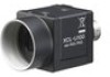
Location and Function of Parts and Operation
 |
View all Sony XCLU100 manuals
Add to My Manuals
Save this manual to your list of manuals |
Page 2 highlights
D E F D CϚϯτʣ C ͝ҙ C 10 mmҎԼͷ 10 mmҎԼ 4 VCT-333I ͢ɻ ޙ໘ E DC INʢDC 12 CCXC-12P05N DCʴ12 V PoCL No ϐϯ൪߸ ৴߸ 1 Ξʔε 2 DCʴ12 V 3 Ξʔε 4 NC 5 Ξʔε 6 NC ϐϯ൪߸ ৴߸ 7 NC 8 Ξʔε 9 NC 10 11 12 Ξʔε ˈˈ12 10 Ξʔε ʗ DVAL DIGITAL IF 26 PoCLରԠͷΧ 26 No.ͱೖग़ྗ ϐϯ൪߸ ৴߸ 1 2 X0 3 X1 4 X2 5 XCLK 6 X3 7 Ser TCʴʢ৴߸ʣ 8 Ser TFGʵʢ৴߸ʣ 9 TRIG 10 NC 11 NC 12 NC 13 INNER_SHIELDʢΞʔεʣ ϐϯ൪߸ ৴߸ 14 INNER_SHIELDʢΞʔεʣ 15 X0 16 X1 17 X2 18 XCLK 19 X3 20 Ser TCʵʢ৴߸ʣ 21 Ser TFGʴʢ৴߸ʣ 22 TRIG 23 NC 24 NC 25 NC 26 ˈˈ26 1൪ϐϯɾ26 PoCL 1൪ϐϯɾ26 POWER PoCL 1൪ϐϯɾ26 INNER_SHIELDʢΞʔεʣ ͝ҙ 26 ৼ෯ɿ LVDSʢ3.3 V ICग़ྗʣ ଓɿ 9൪ϐϯʹTRIG (ʵ) 22൪ϐϯʹTRIG (ʴ) F DC IN DIGITAL IF PoCL DC IN DC INࢠ DIGITAL IFࢠ DC-700 2Խ 3ʷ3ϑΟϧλʔ ༰ ϊʔϚϧ 2 s ʙ 1/10,000 s 2 s ʙ 1/10,000 s τϦΨʔ෯ 0 dB ʙ +18 dB OFF/ON OFF/ONʢϞʔυ1ʙϞʔυ5ʣ 26 12 8Ϗοτʗ 10Ϗοτʗ 12Ϗοτ OFF/ON OFF/ON OFF/ON VCT-333I 4.5 mm ʙ 5.5 mm 0.18Πϯν ʙ 0.22Πϯν CCD CCD CCD ই CCD ന CCD CCD ओͳ༷ 1/1.8ܕCCD 1,628 ʷ1,236 60ըૉ 4.4ʷ4.4 Жm 8.5ʷ6.8 mm CϚϯτ 17.526 mm ෦ LVDS 8 10Ϗοτʗ 12Ϗοτ ସ 235εςοϓʢ8 3,760εςοϓ ʢ12Ϗοτ࣌ʣ 16εςοϓʢ8 256εςοϓ ʢ12Ϗοτ࣌ʣ 16εςοϓʙ243εςοϓʢ8 256εςοϓʙ3,900εςοϓʢ12Ϗοτ࣌ʣ 15 Hz 1,600 ʷ1,200 400 lxɺF5.6ʢ0 dB࣌ʣ 1 lxʢήΠϯʴ18 dB࣌ɺF1.4ʣ 0 dBʙʴ18 dB OFF/ONʢϞʔυ1ʙϞʔυ5ʣ 2 ඵʙ1/10,000ඵ DCʴ12 V (10 Vʙ15 V: DC INࢠʗ 10 Vʙ13 V: DIGITAL IFࢠ) 2.2 W 0 ˆʙ40 ˆ ʵ5 ˆʙʴ45 ˆ ʵ30 ˆʙʴ60 ˆ 20ˋʙ80 20ˋʙ95 10 Gʢ20 Hzʙ200 Hzʣ 70 G 29ʢWʣʷ 29ʢHʣʷ 30ʢDʣmm 55 g 1 1ʣ A VCCI-A English Location and Function of Parts and Operation Front/Top/Bottom D Lens mount (C-mount) Attach any C-mount lens or other optical equipment. Note The lens must not project more than 10 mm (13/32 inch) from the lens mount. Lens mount face 10 mm (13/32 inch) or less Guide screw holes (Top) Guide screw holes / Tripod screw holes (Bottom) When using a tripod, use these four screw holes to attach a VCT-333I tripod adaptor. Reference screw holes (Bottom) These precision screw holes are for locking the camera module. Locking the camera module into these holes secures the optical axis alignment. For details, refer to the User's Guide. Rear E DC IN (DC power input) connector (12-pin) You can connect a CCXC-12P05N camera cable to input the +12 V DC power supply. If you use a camera module interface board with support for PoCL, you can operate the camera without using this connector. The pin configuration of this connector is as follows. (For details on the pin arrangement, see Figure -.) Pin No. 1 2 3 4 5 6 Ground +12 V DC Ground NC Ground NC Signal Pin.No. 7 8 9 10 11 12 Signal NC Ground NC Signal* output Triger pulse input Ground Signal output from the Tenth pin of 12 pins connector You can select one of the following signals according to the setting. Ground / DVAL output / Exposure pules output The default setting in the factory is Ground. DIGITAL IF (Interface) connector (26-pin) You can connect a Camera Link cable to this connector to control a camera module from a host device utilizing the serial communication protocol while outputting a video signal from the camera module. If you use a camera module interface board with support for PoCL, you can also supply power from this connecter. You can input the external trigger signal via the 26-pin connector and operate a camera module in the external trigger mode. The pin configuration of this connector is as follows. (For details on the pin arrangement, see Figure -.) Pin No. 1 2 3 4 5 6 7 8 9 10 11 12 13 Signal Power supply or Ground* X0- output (Signal) X1- output (Signal) X2- output (Signal) XCLK- output (Signal) X3- output (Signal) Ser TC+ (Signal) Ser TFG- (Signal) TRIG- input (Signal) NC NC NC INNER_SHIELD (Ground) Pin.No. Signal 14 INNER_SHIELD (Ground) 15 X0+ output (Signal) 16 X1+ output (Signal) 17 X2+ output (Signal) 18 XCLK+ output (Signal) 19 X3+ output (Signal) 20 Ser TC- (Signal) 21 Ser TFG+ (Signal) 22 TRIG+ input (Signal) 23 NC 24 NC 25 NC 26 Power supply or Ground* ˈˈAbout the 1st pin and 26th pin of the 26-pin connector The connection differs depending on the type of camera module interface board you use. In the case of PoCL support: Both the 1st pin and 26th pin are POWER (power supply) In the case of no PoCL support: Both the 1st pin and 26th pin are INNER_SHIELD (Ground) Note When you operate a camera module by inputting an external trigger signal via the 26-pin connector, make sure to input external trigger signals that meet the following specifications to both the two pins. Specifications for the External Trigger Signal Amplitude: LVDS using a 3.3 volt IC Polarity: positive Connections: Input a TRIG (-) signal to the 9th pin. Input a TRIG (+) signal to the 22nd pin. Connecting the cables F Connect the camera cable to the DC IN connector and the Camera Link cable to the DIGITAL IF cable respectively. If you use a camera module interface board with support for PoCL, you can operate the camera even if you do not connect the camera cable to the DC IN connector. When you connect the Camera Link cable, turn the two fastening screws on the connector to secure the cable tightly. DC IN connector Camera cable Fastening screws DIGITAL IF connector Camera Link cable Connect the other end of the camera cable to the DC-700/700CE and the other end of the Camera Link cable to the camera module interface board. Controlling the camera from the host device You can control the camera from host devices such as a computer. The following table shows the control functions. Control functions Operating mode Shutter speed Gain Partial Scan Gamma control External trigger input Video output switch Binning Binarization 3 × 3 filter Description Normal/Trigger Normal 2 s to 1/10,000 s Trigger edge 2 s to 1/10,000 s Trigger pulse width Setting by trigger pulse width 0 dB to +18 dB OFF/ON OFF/ON (Mode 1 to Mode 5) 26 pin connector / 12 pin connector 8 bits / 10 bits / 12 bits OFF/ON OFF/ON OFF/ON (manual or preset) Note Make sure to supply power to the camera module and confirm that the camera module is operating before inputting a trigger signal. If you input trigger signal to a camera module without the power supplied, this may cause a malfunction of the camera module. Using a tripod To use the tripod, install the tripod adaptor VCT-333I (not supplied) on the camera module. Use a tripod screw with a protrusion () extending from the installation surface, as follows, and tighten it, using a screwdriver. 4.5 mm to 5.5 mm 0.18 inches to 0.22 inches Note If you install a tripod adapter (not supplied), use the screws provided. Typicala CCD Phenomena The following effects on the monitor screen are characteristic of CCD cameras. They do not indicate any fault with the camera module. Smear This occurs when shooting a very bright object such as electric lighting, the sun, or a strong reflection. This phenomenon is caused by an electric charge induced by infrared radiation deep in the photosensor. It appears as a vertical smear, since the CCD imaging element uses an interline transfer system. Vertical aliasing When you shoot vertical stripes or lines, they may appear jagged. Blemishes A CCD image sensor consists of an array of individual sensor elements (pixels). A malfunctioning sensor element will cause a single pixel blemish in the picture. (This is generally not a problem.) White speckles While CCD image pickup device is made by an accurate technique, imperceptible speckless may rarely come up on the screen due to cosmic rays and so on. This is connected to the principle of CCD image pickup device, not a malfunction. And the white speckless are easy to come up in the following conditions. ˎˎUsing the camera in high temperature ˎˎWhen turning up the gain Note If strong light enters a wide area of the screen, the screen may become dark. This is not a malfunction. If this occurs, avoid strong light or adjust the lens iris to reduce the light amount. Specifications Imaging system Pickup device Effective picture elements (horizontal/vertical) Optical blank Cell size (horizontal/vertical) Chip size (horizontal/vertical) Progressive scan 1/1.8 type CCD 1,628 × 1,236 60 elements on each horizontal line 4.4 × 4.4 µm 8.5 × 6.8 mm Optical system and others Lens mount Flange focal length Synchronization Video output Reference video output level: Reference pedestal level: Range of guarantee video output: Output signal frequency Effective lines Sensitivity Minimum illumination Gain γ Read mode Shutter Shutter speed C-mount 17.526 mm Internal LVDS 8 bits (default setting)/10 bits/12 bits switching 235 steps (8 bits) / 3,760 steps (12 bits) 16 steps (8 bits) / 256 steps (12 bits) 16 steps to 243 steps (8 bits) / 256 steps to 3,900 steps (12 bits) 15 Hz (normal mode) 1,600 × 1,200 (horizontal/vertical) 400 lx, F5.6 (0 dB) 1 lx (with the gain control at +18 dB, F1.4) 0 dB to +18 dB OFF/ON (Mode 1 to Mode 5) normal/binning External trigger shutter External trigger shutter: 2 sec. to 1/10,000 sec. Power Power consumption Performance guarantee temperature: Operating temperature: Storage temperature: Operating relative humidity: Storage relative humidity: Vibration resistance Shock resistance External dimension (w/h/d) Mass Accessories +12 V DC (10 V to 15 V: with DC IN connector/ 10 V to 13 V: with DIGITAL IF connector) 2.2 W 0 °C to 40 °C (32 °F to 104 °F) -5 °C to +45 °C (23 °F to 113 °F) -30 °C to +60 °C (-22 °F to 140 °F) 20% to 80% (no condensation) 20% to 95% (no condensation) 10 G (20 Hz to 200 Hz) 70 G 29 × 29 × 30 mm (1 3/16 × 1 3/16 × 1 3/16 inches) (excluding protrusions) About 55 g (1.9 oz) Lens mount cap (1) Operating Instructions (1) Design and specifications are subject to change without notice. IMPORTANT The nameplate is located on the bottom. Note Always verify that the unit is operating properly before use. SONY WILL NOT BE LIABLE FOR DAMAGES OF ANY KIND INCLUDING, BUT NOT LIMITED TO, COMPENSATION OR REIMBURSEMENT ON ACCOUNT OF THE LOSS OF PRESENT OR PROSPECTIVE PROFITS DUE TO FAILURE OF THIS UNIT, EITHER DURING THE WARRANTY PERIOD OR AFTER EXPIRATION OF THE WARRANTY, OR FOR ANY OTHER REASON WHATSOEVER. 한국어 D C-마운트) C 주의점 10 mm 10 mm 이하 4 VCT-333I 뒷면 E DC IN(DC 12 핀) CCXC-12P05N 12 V DC PoCL 핀 번호 1 2 3 4 5 6 12 V DC 핀 번호 7 8 9 10 11 12 12 DVAL DIGITAL IF 26 PoCL 26 핀 번호 1 2 3 4 5 6 7 8 9 10 11 12 13 X0 X1 X2 XCLK X3 Ser TC+(신호) Ser TFG-(신호) TRIG INNER_SHIELD(접지) 핀 번호 14 15 16 17 18 19 20 21 22 23 24 25 26 신호 INNER_SHIELD(접지) X0 X1 X2 XCLK X3 Ser TC-(신호) Ser TFG+(신호) TRIG 26 1번 핀 및 26 PoCL 지원: 1번 핀과 26 POWER PoCL 미지원: 1번 핀과 26 INNER_SHIELD 주의점 26 3.3 볼트 IC LVDS TRIG 9 TRIG 22 F DC IN DIGITAL IF PoCL DC IN DC IN DIGITAL IF DC-700/700CE Binning Binarization 3 × 3 필터 설명 정상 2초-1/10,000초 2초-1/10,000초 0 dB 에서 +18 dB 까지 OFF/ON OFF/ON(모드 1 ~ 모드 5) 26 12 8비트/10비트/12비트 OFF/ON OFF/ON OFF/ON VCT-333I 4.5 mm 에서 5.5 mm 0.18 0.22 인치 CCD 현상 CCD 얼룩 CCD 흠집 CCD CCD CCD 사양 1/1.8형 CCD 1,628 × 1,236 60 4.4 × 4.4 μm 8.5 × 6.8 mm C-마운트 17.526 mm 내부 LVDS 8 10비트/ 12 235스텝(8비트)/3,760스텝(12비트) 16스텝(8비트)/256스텝(12비트) 16스텝-243스텝(8비트)/ 256스텝-3,900스텝(12비트) 15 Hz 1,600 × 1,200 400 lx, F5.6 (0 dB) 1 lx(+18 dB, F1.4 0 dB 에서 +18 dB 까지 OFF/ON(모드 1 ~ 모드 5) 정상/Binning 2초 - 1/10,000초 +12 V DC(10 V 에서 15 V 까지: DC IN 커넥터/10 V 에서 13 V 까지: DIGITAL IF 2.2 W 0 C 에서 40 C 까지 -5 C 에서 +45 C 까지 -30 C 에서 +60 C 까지 20% 에서 80 20% 에서 95 10 G(20 Hz 에서 200 Hz 까지) 70 G 29 × 29 × 30 mm(1 3/16× 1 3/16 × 1 3/16 55 g (1.9 oz 1 1) SONY About the Technical Manual The Operating Instructions describe the functions and use of this product. For more details, see the Technical Manual. Please ask your sales representative about the Technical Manual.
-
 1
1 -
 2
2
 |
 |
