Sony XR-CA600X Installation/Connection
Sony XR-CA600X - Fm/mw/sw Cassette Car Stereo Manual
 |
View all Sony XR-CA600X manuals
Add to My Manuals
Save this manual to your list of manuals |
Sony XR-CA600X manual content summary:
- Sony XR-CA600X | Installation/Connection - Page 1
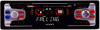
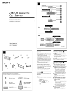
FM/AM Cassette Car Stereo Installation/Connections Installation/Connexions XR-CA610X XR-CA600X Sony Corporation © 2001 Printed in Thailand 1 1 2 3 4 5 6 7 8 × 4 × 2 Equipment used in illustrations (not supplied) Appareils utilisés dans les illustrations (non fournis) Front speaker Haut - Sony XR-CA600X | Installation/Connection - Page 2
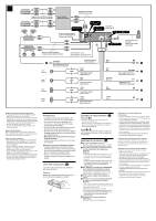
FRONT from car antenna adaptor à partir de l'adaptateur de l'antenne de la voiture L R BUS AUDIO OUT AUDIO OUT AUDIO REAR FRONT 8 Fuse (10 A) Fusible (10 A) BUS CONTROL IN REMOTE XR-CA610X only) (XR instructions. Attention Manipulez précautionneusement le support 1 pour éviter de vous blesser aux - Sony XR-CA600X | Installation/Connection - Page 3
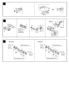
fournies avec la voiture 5 max. size 5 × 8 mm (7/32 × 11/32 in.) Dimension max. 5 × 8 mm (7/32 × 11/32 po.) Bracket Support Bracket Support Existing parts supplied with your car Pièces existantes fournies avec la voiture 5 max. size 5 × 8 mm (7/32 × 11/32 in.) Dimension max. 5 × 8 mm (7/32 × 11 - Sony XR-CA600X | Installation/Connection - Page 4
To attach Place the hole in the front panel onto the spindle on the unit as illustrated, then push the left side in. Mounting the unit in a Japanese car (6) You may not be able to install this unit in some makes of Japanese cars. In such a case, consult your Sony dealer. Note To prevent malfunction
-
 1
1 -
 2
2 -
 3
3 -
 4
4
 |
 |
Sony Corporation
© 2001
Printed in Thailand
XR-CA610X
XR-CA600X
3-227-099-
11
(1)
Equipment used in illustrations (not supplied)
Appareils utilisés dans les illustrations (non fournis)
Cautions
•This unit is designed for negative ground 12 V
DC operation only.
•Do not get the wires under a screw, or caught
in moving parts (e.g. seat railing).
•Before making connections, disconnect the
ground terminal of the car battery to avoid
short circuits.
•Connect the
yellow
and
red
power input leads
only after all other leads have been connected.
•
Run all ground wires to a common ground
point.
•Be sure to insulate any loose unconnected
wires with electrical tape for safety.
Notes on the power supply cord (yellow)
•When connecting this unit in combination with
other stereo components, the connected car
circuit’s rating must be higher than the sum of
each component’s fuse.
•When no car circuits are rated high enough,
connect the unit directly to the battery.
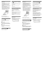
Parts Iist (
1
)
The numbers in the list are keyed to those in the
instructions.
Caution
Handle the bracket
1
carefully to avoid injuring
your fingers.
1
2
B
1
2
×
4
3
4
5
7
8
6
×
2
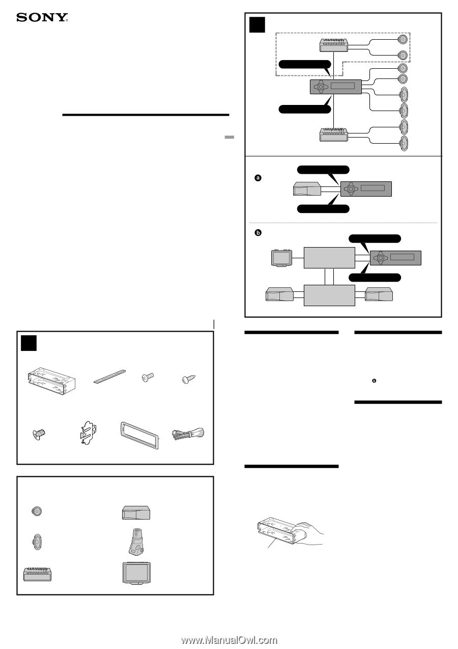
Power amplifier
Amplificateur de puissance
CD/MD changer
Changeur de CD/MD
Front speaker
Haut-parleur frontal
Rear speaker
Haut-parleur arrière
BUS AUDIO IN
BUS CONTROL IN
AUDIO OUT FRONT
Source selector
Sélecteur de source
BUS CONTROL IN
BUS AUDIO IN
A
Installation/Connections
Installation/Connexions
FM
/
AM Cassette
Car Stereo
Connection example (
2
)
Notes
(
2
-A)
• Be sure to connect the ground cord before
connecting the amplifier.
• If you connect an optional power amplifier and
do not use the built-in amplifier, the beep
sound will be deactivated.
Tip
(
2
-B-
)
For connecting two or more changers, the source
selector XA-C30 (optional) is necessary.
Connection diagram (
3
)
1
To a metal surface of the car
First connect the black ground lead, then
connect the yellow and red power input
leads.
2
To the power antenna control lead or power
supply lead of antenna booster amplifier
Notes
• It is not necessary to connect this lead if
there is no power antenna or antenna
booster, or with a manually-operated
telescopic antenna.
• When your car has a built-in FM/AM
antenna in the rear/side glass, see “Notes
on the control and power supply leads.”
3
To AMP REMOTE IN of an optional power
amplifier
This connection is only for amplifiers.
Connecting any other system may damage
the unit.
4
To the interface cable of a car telephone
5
To the +12 V power terminal which is
energized in the accessory position of the
ignition key switch
Notes
• If there is no accessory position, connect to
the +12 V power (battery) terminal which is
energised at all times.
Be sure to connect the black ground to it
first.
• When your car has a built-in FM/AM
antenna in the rear/side glass, see “Notes
on the control and power supply leads.”
6
To the +12 V power terminal which is
energised at all times
Be sure to connect the black ground to it
first.
TV monitor
Moniteur de la télévision
Rotary commander RM-X4S
Satellite de commande
RM-X4S
AUDIO OUT REAR
TV tuner unit
Syntoniseur de
télévision
XR-CA610X only
XR-CA610X seulemente
not supplied
non fourni
*
*
*
1