Stihl BR 550 Technical Guide
Stihl BR 550 Manual
 |
View all Stihl BR 550 manuals
Add to My Manuals
Save this manual to your list of manuals |
Stihl BR 550 manual content summary:
- Stihl BR 550 | Technical Guide - Page 1
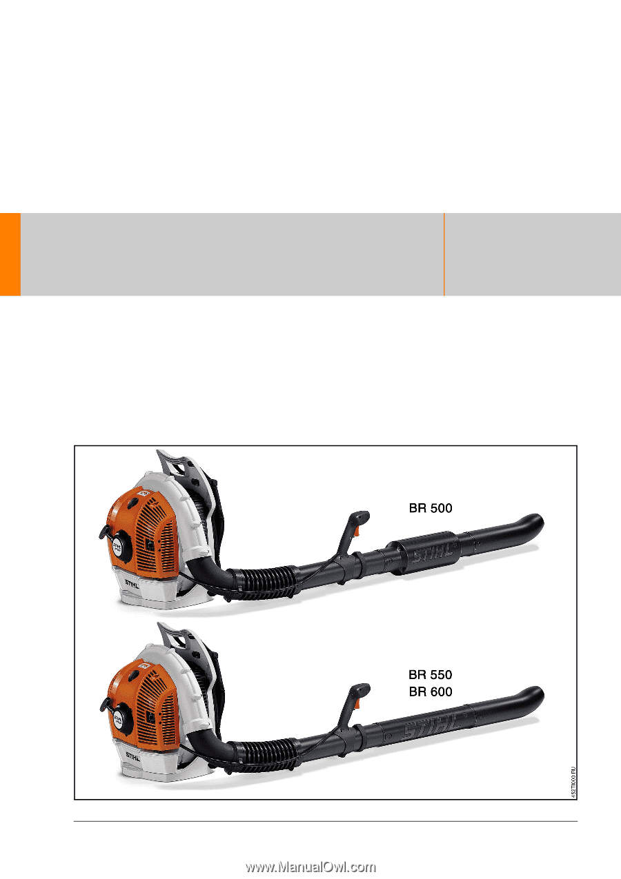
STIH) Technical Information 08.2005 New STIHL BR 500, BR 550 and BR 600 backpack blowers - Series 4282 Contents 1. Technical description 2. Specifications 3. Accessories 4. Service accessories and special tools 5. Service notes TI_08_2005_11_01_02.fm englisch / English - Stihl BR 550 | Technical Guide - Page 2
, professional users. The BR 500 is especially low-noise yet highly powerful for use in noise-sensitive areas. The BR 550 has an attractive price with far aboveaverage blowing strength. The BR 600 is particularly powerful - one of the strongest blowers in the world. The STIHL 4-MIX engine of - Stihl BR 550 | Technical Guide - Page 3
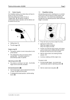
at three levels: 1/3 gas, 2/3 gas and full throttle. . To release the locked position, set the setting lever to #. . Press the fuel pump bulb at least five times. . Setting the choke knob: When the engine is cold l When the engine is hot n . Pull the cord until the engine starts; at the latest, set - Stihl BR 550 | Technical Guide - Page 4
a mixture of petrol and engine oil. This design yields the following advantages: . Same fuel . Lower fuel consumption . Can be operated in all positions . Fewer emissions . Good acceleration . Compact size - attractive design . Advantageous power-to-weight ratio . Easy maintenance - easy to service - Stihl BR 550 | Technical Guide - Page 5
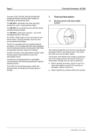
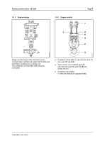
Technical Information 08.2005 Page 5 1.5.1 Engine design 1.5.2 Engine control 7 1 2 6 5 4 254TI011 KN 3 Single-cylinder engine with overhead valves. Cylinder head, cylinder and upper half of crankcase have been combined into a single unit. The crankcase is horizontally split along the - Stihl BR 550 | Technical Guide - Page 6
The engine is lubricated in two phases during each revolution of the crankshaft. Phase 1 The piston rises to the top dead centre. Phase 2 The piston descends to the bottom dead centre. The increase in volume in the crankcase produces a vacuum. From the intake duct (1), the air-fuel-oil mixture is - Stihl BR 550 | Technical Guide - Page 7
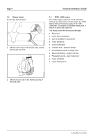
disk when the engine has started: 1.8 Ignition system . Microprocessor-controlled with ignition timing adjustment . Low power-up threshold 1.9 Air filter . Large-area paper air filter for long filter service life . Easily accessible 1.10 Muffler . Two-chamber muffler with spark arresting screen - Stihl BR 550 | Technical Guide - Page 8
limiter caps Low-speed adjusting screw L: 2 turn open High-speed adjusting screw H: 3 1/2 turn open Fuel tank capacity 1.4 l (1400 cm³) 2.3 Ignition system Ignition module: Microprocessor- controlled with adjustment of the ignition timing Spark plug (suppressed): NGK CMR 6 H Electrode gap - Stihl BR 550 | Technical Guide - Page 9
nozzle for BR 500, BR 550 Straight nozzle for BR 600 Bent nozzle for BR 500, BR 550 Bent nozzle for BR 600 BR 500, BR 550, BR 600 Page 9 4. Service accessories and special tools 4.1 Service accessories Part name Grease (225 g tube) Part number 0781 120 1111 Use Oil seals, oil pump drive - Stihl BR 550 | Technical Guide - Page 10
servicing tools To be procured for the first time for the STIHL BR 500, 550, 600: Part name Stop screw Sleeve Part number Use 4282 890 2700 Block crankshaft 5910 893 1704 Fit hookless snap rings in piston The available special tools are listed in the repair instructions for the STIHL BR 500, 550 - Stihl BR 550 | Technical Guide - Page 11
screws or to clean the carburetor. . Remove limiter caps (2) with puller 5910 890 4501 (1). Used caps may not be reused, as they are damaged when pulled off. Adjustment after maintenance / repair . Check air filter and replace it if necessary. . Check spark arresting screen (if installed) - clean - Stihl BR 550 | Technical Guide - Page 12
speed with the high-speed adjusting screw (H): BR 500: 5,500 rpm BR 550: 6,100 rpm BR 600: 7,200 rpm If you make the setting too lean it will increase the risk of engine damage through lack of lubrication and overheating. 6. Continue with "securing the limiter caps". Used caps may not be reused, as - Stihl BR 550 | Technical Guide - Page 13
Kit 4282 007 1001 "Parts for adjusting valve clearance" must be used for this purpose. The kit comprises a setting gauge, O-ring and gasket. 5.4.1 Preparatory steps . Remove the shroud with rewind starter . Remove the lines from the ignition module . Remove the air guide shroud. . Unscrew spark plug - Stihl BR 550 | Technical Guide - Page 14
stroke. In a 4-MIX engine, the power stroke is executed once in every two revolutions of the crankshaft. The piston consequently passes through the top dead centre twice in order to execute one power stroke. Refer to the STIHL Service Training System "Carburetor", under the heading four-stroke - Stihl BR 550 | Technical Guide - Page 15
move and the piston is now in the top dead centre for ignition. . Turn the crankshaft back anticlockwise approx.1/4 turn and then slowly turn it clockwise again until the tip of the flywheel is lined up with the ignition coil. The crankshaft must be turned backwards in order to eliminate the flank - Stihl BR 550 | Technical Guide - Page 16
is flush with the ignition coil. . Check the valve clearance again and re-adjust if necessary . Fit gasket (1) in position (arrows) . Fit valve cover and tighten screw with a torque of 6 Nm . Mount the air guide shroud . Screw in spark plug, fit shroud, and plug in spark plug boot . Fit starter - Stihl BR 550 | Technical Guide - Page 17
hazard! . Remove the ignition system tester from the spark plug, and screw out the spark plug. . Screw in compression tester 5910 850 2000 (1) into the sparkplug hole. While using the ZAT 3, hold it only by the handle (4) or position it in a safe place. Fingers and other body parts must be at least - Stihl BR 550 | Technical Guide - Page 18
clip without the retention groove for the throttle cable) - screw head facing forward. . Run the arrester (1) through the pleated hose (7). . Shove blower tube (3) onto blower tube (2), and lock the buttons (4) . Shove the blower tube (2) into the pleated hose (7). . Tighten the hose clip (6) with - Stihl BR 550 | Technical Guide - Page 19
hose (7) and hose clip (9) (hose clip with the retention groove for the throttle cable) - screw head and retention groove facing forward. . Shove nozzle (13) (depending on the market region) onto blower tube (2), and lock the buttons (14). Only operate the device when the arrester is correctly - Stihl BR 550 | Technical Guide - Page 20
may have to be readjusted. 5.8 Install tank vent The throttle cable may only be adjusted when the blower is completely assembled. . Pull the throttle trigger all the way back. . Carefully turn the screw in the throttle trigger until it starts to encounter resistance. Tank vents must not be reused - Stihl BR 550 | Technical Guide - Page 21
connecting element (1) with the hoses and pick-up body. . Replace the pick-up body. Do not confuse the hose for the fuel return (2) and suction hose (3): The suction hose (3) has ) must lie in the recess of the fuel tank. . Press in the connecting element until it locks; it must audibly snap in. - Stihl BR 550 | Technical Guide - Page 22
run 6 Cylinder, piston, pressure test * 7 Ignition system, contact 8 Fuel supply, tank vent, test run 9 Manifold or flange, pressure test 10 Carburetor, testing* 11 Blower tube and throttle control 12 Starter with trial run 13 Clutch, trial run 14 Muffler 15 Air filter 16 Stop switch with trial run
-
 1
1 -
 2
2 -
 3
3 -
 4
4 -
 5
5 -
 6
6 -
 7
7 -
8
-
9
-
10
-
11
-
12
-
13
-
14
-
15
-
16
-
17
-
18
-
19
-
20
-
21
-
22
 |
 |
STIH)
Technical Information
TI_08_2005_11_01_02.fm
englisch / English
New STIHL BR 500, BR 550 and BR 600 backpack blowers – Series 4282
Contents
1.
Technical description
2.
Specifications
3.
Accessories
4.
Service accessories and special tools
5.
Service notes
08.2005