TP-Link T1500G-10MPS T1500G-10MPSUN V1 User Guide - Page 108
Network Diagram, Configuration Procedure, Operation, Description, 1Q VLAN
 |
View all TP-Link T1500G-10MPS manuals
Add to My Manuals
Save this manual to your list of manuals |
Page 108 highlights
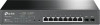
Multicast source sends multicast streams via the router, and the streams are transmitted to user A and user B through the switch. Router: Its WAN port is connected to the multicast source; its LAN port is connected to the switch. The multicast packets are transmitted in VLAN3. Switch: Port 3 is connected to the router and the packets are transmitted in VLAN3; port 4 is connected to user A and the packets are transmitted in VLAN4; port 5 is connected to user B and the packets are transmitted in VLAN5. User A: Connected to Port 4 of the switch. User B: Connected to port 5 of the switch. Configure a multicast VLAN, and user A and B receive multicast streams through the multicast VLAN. Network Diagram Configuration Procedure Step Operation 1 Create VLANs 2 Configure ports Description Create three VLANs with the VLAN ID 3, 4 and 5 respectively, and specify the description of VLAN3 as Multicast VLAN on VLAN→802.1Q VLAN page. On VLAN→802.1Q VLAN function pages. For port 3, configure its link type as Tagged, and add it to VLAN3, VLAN4 and VLAN5. For port 4, configure its link type as Untagged, and add it to VLAN3 and VLAN4. For port 5, configure its link type as Untagged, and add it to VLAN3 and VLAN5. 99
-
 1
1 -
2
-
3
-
4
-
5
-
6
-
7
-
8
-
9
-
10
-
11
-
12
-
13
-
14
-
15
-
16
-
17
-
18
-
19
-
20
-
21
-
22
-
23
-
24
-
25
-
26
-
27
-
28
-
29
-
30
-
31
-
32
-
33
-
34
-
35
-
36
-
37
-
38
-
39
-
40
-
41
-
42
-
43
-
44
-
45
-
46
-
47
-
48
-
49
-
50
-
51
-
52
-
53
-
54
-
55
-
56
-
57
-
58
-
59
-
60
-
61
-
62
-
63
-
64
-
65
-
66
-
67
-
68
-
69
-
70
-
71
-
72
-
73
-
74
-
75
-
76
-
77
-
78
-
79
-
80
-
81
-
82
-
83
-
84
-
85
-
86
-
87
-
88
-
89
-
90
-
91
-
92
-
93
-
94
-
95
-
96
-
97
-
98
-
99
-
100
-
101
-
102
-
 103
103 -
 104
104 -
 105
105 -
 106
106 -
 107
107 -
 108
108 -
 109
109 -
 110
110 -
 111
111 -
 112
112 -
 113
113 -
114
-
115
-
116
-
117
-
118
-
119
-
120
-
121
-
122
-
123
-
124
-
125
-
126
-
127
-
128
-
129
-
130
-
131
-
132
-
133
-
134
-
135
-
136
-
137
-
138
-
139
-
140
-
141
-
142
-
143
-
144
-
145
-
146
-
147
-
148
-
149
-
150
-
151
-
152
-
153
-
154
-
155
-
156
-
157
-
158
-
159
-
160
-
161
-
162
-
163
-
164
-
165
-
166
-
167
-
168
-
169
-
170
-
171
-
172
-
173
-
174
-
175
-
176
-
177
-
178
-
179
-
180
-
181
-
182
-
183
-
184
-
185
-
186
-
187
-
188
-
189
-
190
-
191
-
192
-
193
-
194
-
195
-
196
-
197
-
198
-
199
-
200
-
201
-
202
-
203
-
204
-
205
-
206
-
207
-
208
-
209
-
210
-
211
-
212
-
213
-
214
-
215
-
216
-
217
-
218
-
219
-
220
-
221
-
222
-
223
-
224
-
225
-
226
-
227
-
228
-
229
-
230
-
231
-
232
-
233
-
234
 |
 |
