Toshiba 20AF41 Service Manual - Page 8
Service Mode List, Confirmation Of Using Hours, Note For The Replacing Of Memory Ic - operating without remote
 |
View all Toshiba 20AF41 manuals
Add to My Manuals
Save this manual to your list of manuals |
Page 8 highlights
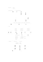
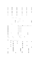
SERVICE MODE LIST This unit provided with the following SERVICE MODES so you can repair, examine and adjust easily. To enter the Service Mode, press both set key and remote control key for more than 1 second. Set Key Remocon Key VOL. (-) MIN 0 VOL. (-) MIN 1 Operations Releasing of V-CHIP PASSWORD. Initialization of the factory. NOTE: Do not use this for the normal servicing. VOL. (-) MIN 6 POWER ON total hours is displayed on the screen. Refer to the "CONFIRMATION OF USING HOURS". Can be checked of the INITIAL DATA of MEMORY IC. Refer to the "NOTE FOR THE REPLACING OF MEMORY IC". VOL. (-) MIN 8 Writing of EEPROM initial data. NOTE: Do not use this for the normal servicing. VOL. (-) MIN 9 Display of the Adjustment MENU on the screen. Refer to the "ELECTRICAL ADJUSTMENT" (On-Screen Display Adjustment). CONFIRMATION OF USING HOURS POWER ON total hours can be checked on the screen. Total hours are displayed in 16 system of notation. 1. Set the VOLUME to minimum. 2. Press both VOL. DOWN button on the set and Channel button (6) on the remote control for more than 1 second. 3. After the confirmation of using hours, turn off the power. ADDRESS DATA INIT 00 83 CRT ON 0010 FIG. 1 Initial setting content of MEMORY IC. POWER ON total hours. = (16 x 16 x 16 x thousands digit value) + (16 x 16 x hundreds digit value) + (16 x tens digit value) + (ones digit value) NOTE FOR THE REPLACING OF MEMORY IC If a service repair is undertaken where it has been required to change the MEMORY IC, the following steps should be taken to ensure correct data settings while making reference to TABLE 1. INI +0 +1 +2 +3 +4 +5 +6 +7 +8 +9 +A +B +C +D +E +F 00 A1 C3 CF 00 31 B3 27 37 BE E8 F4 84 00 00 00 46 10 40 Table 1 1. Enter DATA SET mode by setting VOLUME to minimum. 2. Press both VOL. DOWN button on the set and Channel button (6) on the remote control for more than 1 second. ADDRESS and DATA should appear as FIG 1. 3. ADDRESS is now selected and should "blink". Using the VOL. UP/DOWN button on the remote, step through the ADDRESS until required ADDRESS to be changed is reached. 4. Press ENTER to select DATA. When DATA is selected, it will "blink". 5. Again, step through the DATA using VOL. UP/DOWN button until required DATA value has been selected. 6. Pressing ENTER will take you back to ADDRESS for further selection if necessary. 7. Repeat steps 3 to 6 until all data has been checked. 8. When satisfied correct DATA has been entered, turn POWER off (return to STANDBY MODE) to finish DATA input. The unit will now have the correct DATA for the new MEMORY IC.
-
 1
1 -
2
-
 3
3 -
 4
4 -
 5
5 -
 6
6 -
 7
7 -
 8
8 -
 9
9 -
 10
10 -
 11
11 -
 12
12 -
 13
13 -
14
-
15
-
16
-
17
-
18
-
19
-
20
-
21
-
22
-
23
-
24
-
25
-
26
-
27
-
28
-
29
-
30
-
31
-
32
-
33
-
34
-
35
-
36
-
37
 |
 |
