Toshiba 20AF41 Service Manual - Page 9
Electrical Adjustments - tv repair
 |
View all Toshiba 20AF41 manuals
Add to My Manuals
Save this manual to your list of manuals |
Page 9 highlights
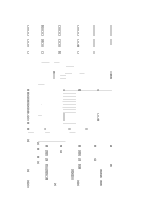
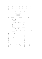
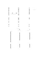
ELECTRICAL ADJUSTMENTS 1. BEFORE MAKING ELECTRICAL ADJUSTMENTS Read and perform these adjustments when repairing the circuits or replacing electrical parts or PCB assemblies. CAUTION • Use an isolation transformer when performing any service on this chassis. • Before removing the anode cap, discharge electricity because it contains high voltage. • When removing a PCB or related component, after unfastening or changing a wire, be sure to put the wire back in its original position. Inferior silicon grease can damage IC's and transistors. • When replacing IC's and transistors, use only specified silicon grease. Remove all old silicon before applying new silicon. Prepare the following measurement tools for electrical adjustments. 1. Synchro Scope 2. Digital Voltmeter On-Screen Display Adjustment 1. In the condition of NO indication on the screen. Press the VOL. DOWN button on the set and the Channel button (9) on the remote control for more than 1 second to appear the adjustment mode on the screen as shown in Fig. 1-1. TV 00 OSD 15 Fig. 1-1 2. Use the Channel UP/DOWN button or Channel button (0-9) on the remote control to select the options shown in Fig. 1-2. 3. Press the MENU button on the remote control to end the adjustments. 2. BASIC ADJUSTMENTS 2-1: CONSTANT VOLTAGE 1. Set condition is AV MODE without signal. 2. Connect the digital voltmeter to TP002. 3. Adjust the VR502 until the digital voltmeter is 111 ± 1V. 2-2: RF AGC 1. Receive a 70dB monoscope pattern. 2. Connect the digital voltmeter between the TP001 and the GND. 3. Activate the adjustment mode display of Fig. 1-1 and press the channel button (02) on the remote control to select "RF. AGC". 4. Press the VOL. UP/DOWN button on the remote control until the digital voltmeter is 1.95 ± 0.05V. 2-3: CUT OFF 1. Adjust the unit to the following settings. G. DRIVE=64, B. DRIVE=64, R. BIAS=32, G. BIAS=32, B. BIAS=32, BRIGHTNESS=70, UNI COLOR=64. 2. Place the set with Aging Test for more than 15 minutes. 3. Activate the adjustment mode display of Fig. 1-1 and press the channel button (01) on the remote control to select "CUT OFF". 4. Adjust the Screen Volume until a dim raster is obtained. 2-4: WHITE BALANCE NOTE: Adjust after performing CUT OFF adjustment. 1. Place the set with Aging Test for more than 10 minutes. 2. Receive the white 100% signal from the Pattern Generator. 3. Using the adjustment control, set the brightness and contrast to normal position. 4. Activate the adjustment mode display of Fig. 1-1 and press the channel button (13) on the remote control to select "R. BIAS". 5. Using the VOL. UP/DOWN button on the remote control, adjust the R. BIAS. 6. Press the CH. UP/DOWN button on the remote control to select the "G. DRV", "B. DRV", "G. BIAS" or "B. BIAS". 7. Using the VOL. UP/DOWN button on the remote control, adjust the G. DRV, B. DRV, G. BIAS or B. BIAS. 8. Perform the above adjustments 6 and 7 until the white color is looked like a white. NO. FUNCTION 00 OSD H 01 CUT OFF 02 RF. AGC 03 --04 H. POSI 05 V. POSI 06 H. SIZE 07 V. SIZE 08 V. CENT 09 V. LIN 10 VS. CORR 11 G. DRV 12 B. DRV 13 R. BIAS 14 G. BIAS 15 B. BIAS 16 BRI NO. FUNCTION 17 SUBCONT 18 UNI COL 19 --20 TINT 21 SHARP 22 RGB CONT 23 PARABOLA 24 TRAPEZIU 25 COR TOP 26 COR BTM 27 V EHT 28 H EHT 29 FM. LVL 30 LEVEL 31 SEP1 32 SEP2 33 T. STE Fig. 1-2 2-5: FOCUS 1. Receive a 70dB monoscope pattern. 2. Turn the Focus Volume fully counterclockwise once. 3. Adjust the Focus Volume until picture is distinct. 2-6: HORIZONTAL POSITION 1. Receive the center cross signal from the Pattern Generator. 2. Using the remote control, set the brightness and contrast to normal position. 3. Activate the adjustment mode display of Fig. 1-1 and press the channel button (04) on the remote control to select "H. POSI". 4. Press the VOL. UP/DOWN button on the remote control until the right and left screen size of the vertical line becomes the same.
-
 1
1 -
2
-
3
-
 4
4 -
 5
5 -
 6
6 -
 7
7 -
 8
8 -
 9
9 -
 10
10 -
 11
11 -
 12
12 -
 13
13 -
 14
14 -
15
-
16
-
17
-
18
-
19
-
20
-
21
-
22
-
23
-
24
-
25
-
26
-
27
-
28
-
29
-
30
-
31
-
32
-
33
-
34
-
35
-
36
-
37
 |
 |
