Toshiba DVR610 Service Manual
Toshiba DVR610 - DVDr/ VCR Combo Manual
 |
UPC - 022265001370
View all Toshiba DVR610 manuals
Add to My Manuals
Save this manual to your list of manuals |
Toshiba DVR610 manual content summary:
- Toshiba DVR610 | Service Manual - Page 1
FILE NO. 810-200803GR DVD Video Recorder /Video Cassette Recorder D-VR610KU The above model is classified as a green product (*1), as indicated by the underlined serial number. This Service Manual describes replacement parts for the green product. When repairing this green product, use the part - Toshiba DVR610 | Service Manual - Page 2
and scope of its environmental activities. In line with this, Toshiba proactively promotes Green Procurement, and seeks to purchase and use responsible. Lead-free solder must be used in the servicing and repair of this product. WARNING This product is manufactured using lead free solder. DO - Toshiba DVR610 | Service Manual - Page 3
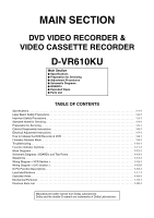
Precautions 1-3-1 Standard Notes for Servicing 1-4-1 Preparation for Servicing 1-5-1 Cabinet Disassembly Instructions 1-6-1 Electrical Adjustment Instructions 1-7-1 How to Initialize the DVD Recorder & VCR 1-8-1 Firmware Renewal Mode 1-9-1 Troubleshooting 1-10-1 Function Indicator Symbols - Toshiba DVR610 | Service Manual - Page 4
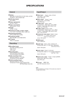
SPECIFICATIONS General System DVD-RW/-R, DVD+RW/+R, DVD-video, CD-DA, CD-RW/-R, VHS cassette tape VCR Video Heads Four heads Power Recording Recording format VR (video recording) format Video format +VR format Recording discs DVD-Rewritable/-Recordable, DVD+Rewritable/+Recordable Video recording - Toshiba DVR610 | Service Manual - Page 5
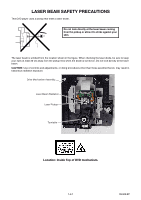
LASER BEAM SAFETY PRECAUTIONS This DVD player uses a pickup that emits a laser beam. Do not look the diode is turned on. Do not look directly at the laser beam. CAUTION: Use of controls and adjustments, or doing procedures other than those specified herein, may result in hazardous radiation exposure - Toshiba DVR610 | Service Manual - Page 6
components rated for review continuously and new instructions codes of the countries in which they are to be sold. However, in order to maintain such compliance, it is equally important to implement the following precautions when a set is being serviced. Precautions during Servicing Insulation tape - Toshiba DVR610 | Service Manual - Page 7
Safety Check after Servicing Examine the area surrounding the repaired location for damage or Part Z AC Voltmeter (High Impedance) B Earth Ground Power Cord Plug Prongs Fig. 2 Table 2: Leakage current ratings for selected areas AC Line Voltage 120 V Load Z 0.15 μF CAP. & 1.5 kΩ RES. Connected - Toshiba DVR610 | Service Manual - Page 8
SERVICING NOTE: BOARD MEANS PRINTED CIRCUIT BOARD. Circuit Board Indications 1. The output pin of the 3 pin Regulator ICs is indicated as shown. Top View Input Out In Bottom View 2. For other ICs, pin 1 and every fifth pin are indicated as shown. 5 Pin 1 Pb (Lead) Free Pin 1 Instructions for - Toshiba DVR610 | Service Manual - Page 9
solder flux which is applied to all pins of the flat pack-IC, you can remove it easily. (Fig. S-1-3) Flat Pack-IC Desoldering Braid Masking Tape Tweezers Flat Pack-IC Fig. S-1-2 Soldering Iron Fig. S-1-3 2. Lift each lead of the flat pack-IC upward one by one, using a sharp pin or wire - Toshiba DVR610 | Service Manual - Page 10
With Iron Wire: 1. Using desoldering braid, remove the solder from all pins of the flat pack-IC. When you use solder flux which is applied to all pins of the flat pack-IC, you can remove it easily. (Fig. S-1-3) 2. Affix the wire to a workbench or solid mounting point, as shown in Fig. S-1-5. 3. - Toshiba DVR610 | Service Manual - Page 11
Instructions for Handling Semiconductors Electrostatic breakdown of the semi-conductors may occur due to a potential difference caused by electrostatic charge during unpacking or repair work. 1. Ground - Toshiba DVR610 | Service Manual - Page 12
End Sensors on this equipment. Carefully read and follow the instructions below. Otherwise the unit may operate erratically. What to do for preparation Insert a tape into the Deck Mechanism Assembly and press the [ O ] (VCR) button. The tape will be loaded into the Deck Mechanism Assembly. Make sure - Toshiba DVR610 | Service Manual - Page 13
INSTRUCTIONS NOTE: BOARD MEANS PRINTED CIRCUIT BOARD. 1. Disassembly Flowchart This flowchart indicates the disassembly steps to gain access to item(s) to be serviced Deck Assembly [16] BOARD Power Switch [17] BOARD DVD open /close Switch [14] VCR Chassis Unit [18] BOARD Main [19] Deck Pedestal - Toshiba DVR610 | Service Manual - Page 14
Gear with the hole of LD-SW as shown in Fig. D9. 4. The DVD Mechanism & DVD Main BOARD Assembly is adjusted as a unit at factory. Therefore, do not disassemble it. Replace the DVD Mechanism & DVD Main BOARD Assembly as a unit. (S-1) [1] Cover Top (S-1) (S-5) [4] Jack Bracket [5] BOARD Front Jack - Toshiba DVR610 | Service Manual - Page 15
Fig. D5 (S-10) CN1101 (S-14) Fig. D7 (S-13) (S-14) Board Washer (S-16) [10] Motor DC Fan [9] Fan Holder Fig. D6 (S-17) (S-18) (S-15) (S-14) [14] VCR Chassis Unit 1-6-3 Fig. D8 E9KGADC - Toshiba DVR610 | Service Manual - Page 16
Head Assembly Pin SW1512 LD-SW [16] BOARD Power Switch (S-19) Lead with blue stripe Desolder [18] BOARD Main [18] BOARD Main (S-20) [17] BOARD DVD open/close Switch Desolder Lead with blue stripe [15] Deck Assembly Shaft Cam Gear Hole Hole LD-SW Pin [18] BOARD Main From Capstan Motor - Toshiba DVR610 | Service Manual - Page 17
(S-21) (S-21) (S-21) (S-21) [19] Deck Pedestal [20] Front Bracket R DV Plate Earth (S-22) DV Jack (S-23) Fig. D10 1-6-5 E9KGADC - Toshiba DVR610 | Service Manual - Page 18
Remove the Cover Top. 2. Remove the Panel Front. 3. Remove the Front Bracket. 4. Remove the DVD Mechanism & DVD Main BOARD Assembly. 5. Unhook two places and detach the Dust Cover. 6. Rotate the gear in the direction of the arrow manually as shown below until the tray descends. 7. Pull the tray out - Toshiba DVR610 | Service Manual - Page 19
INSTRUCTIONS , make sure that the tracking control is set in the center position VCR) button on the front panel. Test Equipment Required 1.Oscilloscope: Dual-trace with 10:1 probe, V-Range: 0.001~50V/Div., F-Range: DC~AC-20MHz 2.Alignment Tape BOARD MAIN) PLAY (SP) ----- Tape Measurement Equipment - Toshiba DVR610 | Service Manual - Page 20
the DVD recorder & VCR as the following procedure. < DVD Section > 1. Turn the DVD recorder on. 2. Confirm that no disc is loaded or that the disc tray is open. To put the DVD recorder into the Version display mode, press [DVD], [INSTANT SKIP], [1], [2], and [3] buttons on the remote control unit - Toshiba DVR610 | Service Manual - Page 21
DVD recorder into version up mode, press [INSTANT SKIP], [6], [5], and [4] buttons on the remote control unit in the order. Then the tray will open automatically. Fig. a appears on the screen and Fig. b appears on the VFD. * Firmware will start automatically. * Firmware Version differs depending on - Toshiba DVR610 | Service Manual - Page 22
TROUBLESHOOTING NOTE: BOARD MEANS PRINTED CIRCUIT BOARD. 1 Power Supply Section FLOW CHART shorted in each rectifying circuit of secondary side and replace P1 (BOARD MCV) if defective. After servicing, replace the fuse (F1001). FLOW CHART NO.3 When the output voltage fluctuates. Does the secondary - Toshiba DVR610 | Service Manual - Page 23
FLOW CHART NO.6 P-ON+9V is not outputted. No Is 12V voltage supplied to the collector of Q1055? Yes No Is 10V voltage supplied to the base of Q1055? Yes Check Q1055 and their periphery, and replace P1 (BOARD MCV) if defective. Check D1014, D1017, C1012, and their periphery, and replace P3 (BOARD - Toshiba DVR610 | Service Manual - Page 24
FLOW CHART NO.10 P-ON+5V is not outputted. (P-ON +11V is outputted normally.) No Is 5V voltage supplied to the collector of Q1101? Yes Check Q1101 and their periphery, and replace P1 (BOARD MCV) if defective. Check D1015, D1016, C1017, C1019, L1012 and their periphery, and replace P3 (BOARD POWER - Toshiba DVR610 | Service Manual - Page 25
of IC1501-85 4.30 3.60 2.90 2.39 1.98 1.61 1.27 0.92 0.51 (V) KEY-2 IC1501-85 S-INH ----- DUBBING DVD REC /OTR OPEN/ CLOSE ----- DVD PLAY ----- DVD STOP FLOW CHART NO.2 No operation is possible from the remote control unit. (Operation is possible from the unit.) Is 5V voltage supplied to the Pin - Toshiba DVR610 | Service Manual - Page 26
disc tray cannot be opened and closed. [No Disc] indicated. Both functions of picture and sound do not operate normally. Replace P2 (DVD MECHANISM & DVD MAIN BOARD ASSEMBLY). FLOW CHART NO.5 VIDEO E-E does not appear normally. Are the video signals inputted to each pin of IC2805? IC2805 IC2805 - Toshiba DVR610 | Service Manual - Page 27
A Are the video signals shown above inputted into each pin of IC2404 and each pin of IC2405? No IC2405 IC2405 IC2405 IC2404 IC2404 3PIN 8PIN 6PIN 3PIN 1PIN VIDEO-Y(I/P) VIDEO-Pr/Cr VIDEO-Pb/Cb VIDEO-Y(I) VIDEO-C Yes Are the video signals outputted to each pin of No IC2404 and each pin of - Toshiba DVR610 | Service Manual - Page 28
Check the line between the emitter of Q2391 and JK2751, and replace P1 (BOARD MCV) if defective. No Replace P1 (BOARD MCV). Replace P2 (DVD MECHANISM & DVD MAIN BOARD ASSEMBLY). Check the line between each pin of CN2201 and each pin of IC2404 and IC2405, and replace P1 (BOARD MCV) if defective - Toshiba DVR610 | Service Manual - Page 29
between Pin(9, 10) of IC2801 and Pin(60,61) of IC1501, and replace P1 (BOARD MCV) if defective. Replace P1 (BOARD MCV). Replace P2 (DVD MECHANISM & DVD MAIN BOARD ASSEMBLY). Check each line between each pin of CN2201 and each pin of IC2804, and replace P1 (BOARD MCV) if defective. CN2201 17PIN - Toshiba DVR610 | Service Manual - Page 30
(JK2751)? Yes Check the line between Pin(4,14) of IC2406 and audio terminal (JK2751), and replace P1 (BOARD MCV) if defective. Replace P2 (DVD MECHANISM & DVD MAIN BOARD ASSEMBLY). Check each line between each pin of CN2201 and each pin of IC2804, and replace P1 (BOARD MCV) if defective. CN2201 - Toshiba DVR610 | Service Manual - Page 31
2.90 2.39 1.98 1.61 1.27 0.92 0.51 (V) KEY-1 IC1501-86 CH DOWN CH UP D/V OUTPUT REC /OTR FF REW PLAY STOP /EJECT POWER FLOW CHART NO.2 No VCR operation is possible from the remote control unit. (Operation is possible from the unit.) Is 5V voltage supplied to the Pin(3) terminal of No the RS1501 - Toshiba DVR610 | Service Manual - Page 32
on Pin(81) of No IC1501, does the "L" pulse switch to the "H" pulse? Yes When loading a cassette tape, does the LD-SW No operate normally? Yes Replace P1 (BOARD MCV). FLOW CHART NO.5 Cassette tape can not be ejected. When pressing the eject button, does the Capstan No Motor start rotating? Yes - Toshiba DVR610 | Service Manual - Page 33
FLOW CHART NO.6 Capstan Motor does not rotate. Is 5V voltage supplied to Pin(2) of CN1502? No Yes Is over approximately 2.6V voltage supplied to No Pin(5) of CN1502? Yes Is 12V voltage supplied to Pin(1,11) of CN1502? No Yes Replace 1B1 (DECK ASSEMBLY). FLOW CHART NO.7 Drum Motor does not - Toshiba DVR610 | Service Manual - Page 34
FLOW CHART NO.10 Video E-E does not appear. Are the video signals inputted to each pin of IC2805? No IC2805 IC2805 8PIN 10PIN VIDEO-IN1 (REAR) VIDEO-IN2 (FRONT) Yes No Is the video signal ouputtted to Pin(20) of IC2805? Yes No Is the video signal inputted to Pin(30) of IC1301? Yes Check the - Toshiba DVR610 | Service Manual - Page 35
C Is the video signal outputted to Pin(15) of IC2406? No Yes Is the video signal outputted to the emitter of Q2391? Yes No Check the line between Pin(15) of IC2406 and Q2391, and replace P1 (BOARD MCV) if defective. Check the line between the emitter of Q2391 and the video output terminal ( - Toshiba DVR610 | Service Manual - Page 36
Pin(9,10,11) of IC2406? Yes No Replace P1 (BOARD MCV). Replace P1 (BOARD MCV). FLOW CHART NO.12 Hi-Fi audio can not be recorded normally. (E-E mode is normal.) No Is the REC FM signal outputted to Pin(26) of IC1451? Yes Is the line between Pin(8) of CN1253 and - Toshiba DVR610 | Service Manual - Page 37
between Pin(39) of IC1451 and Pin(30) of IC1501, and replace P1 (BOARD MCV) if defective. FLOW CHART NO.14 Audio can not be recorded normally in the linear audio mode. (E-E mode is normal.) No Is the audio signal inputted into Pin(76,78,80) of IC1301? Yes No Does - Toshiba DVR610 | Service Manual - Page 38
FUNCTION INDICATOR SYMBOLS < VCR Section > Note: If a mechanical malfunction occurs, the power is 0 : 00 : 00 A D SP 0 : 00 : 00 Recording mode Elapsed time Fig. 1 When tape loading mechanism is not functioning correctly Recording mode Elapsed time P-ON Power safety detection Fig. 4 A T SP - Toshiba DVR610 | Service Manual - Page 39
22 Disc Error has occurred. 3 23 The -R Disc of VR Mode. 6 24 The disc except for finalized DVD-R/RW/ +R/+RW. 1 This program is not allowed to You cannot record copy be recorded. prohibited programs. 25 During the Macrovision picture input. 11 26 During the CGMS picture input. 12 This - Toshiba DVR610 | Service Manual - Page 40
The 999 chapter has been reached. (VR Format Disc) 9 You cannot record on this disc as Control Information is full. Delete unnecessary titles. 34 There is not space to record field of control information. 10 You cannot record on the disc as Power Calibration Area is Insert a new disc. 35 - Toshiba DVR610 | Service Manual - Page 41
DVD OPEN/CLOSE SWITCH AL+5V AUDIO-SW1 61 AUDIO-SW2 60 SW1617 DUBBING CN2210 1 DUBBING-SW SW1615 2 OPEN/CLOSE-SW OPEN/CLOSE CN2209 1 2 TP502 S-INH KEY SWITCH (DVD 1-12-1 VCR-LED 94 VCR-LED 95 DVD-LED 96 DVD-LED 97 D1563 D1562 VCR DVD AL+5V IC101 MAIN MICRO CONTROLLER SYS-RESET 44 - Toshiba DVR610 | Service Manual - Page 42
SENSOR Q1503 END-S BOARD SENSOR CYLINDER ASSEMBLY PG SENSOR M DRUM MOTOR LOADING M MOTOR CAPSTAN MOTOR CAPSTAN MOTOR M MOTOR DRIVE CIRCUIT BOARD MAIN IC1501 (SERVO CONTROL) TP506 TP505 TP507 ST-S T-REEL END-S Q1506 T-REEL TP513 CTL SW1512 AL+5V(1) MODE-SW 76 CTL 74 CTL(+) 75 CTL(-) 87 LD - Toshiba DVR610 | Service Manual - Page 43
MOTOR DRIVER DVD MAIN BOARD REC VIDEO SIGNAL PB VIDEO SIGNAL REC AUDIO SIGNAL PB AUDIO SIGNAL IC101 (MAIN MICRO CONTROLLER/MPEG2 AV 2 AC1 3 AUDIO (L)-OUT AUDIO (R)-OUT SPDIF AIMS MD MC SYSCLK LRCK BCK DATA DVD-AUDIO-MUTE TO AUDIO INPUT/ OUTPUT SELECT BLOCK DIAGRAM TO DV JACK CN901 (W2) - Toshiba DVR610 | Service Manual - Page 44
VIDEO SIGNAL BOARD MAIN PB VIDEO SIGNAL TO VIDEO INPUT SELECT BLOCK DIAGRAM VCR-VIDEO TO VIDEO OUTPUT SELECT BLOCK DIAGRAM (DVD VCR DUBBING) DVD-VIDEO(DUB) TO SYSTEM CONTROL BLOCK DIAGRAM YCA-SCL YCA-SDA YCA-CS C-SYNC D-V-SYNC 30 VCR DVD 28 VIDEO AGC FBC Y/C MIX RP 53 54 55 25 24 D-V-SYNC - Toshiba DVR610 | Service Manual - Page 45
VIDEO1 8 VIDEO2 10 PB/EE 12 MUTE (VCR DVD DUBBING) VCR-VIDEO(DUB) TO VIDEO BLOCK DIAGRAM YC G G JK2401 S-VIDEO IN1 REAR JK2804 VIDEO - IN1 VIDEO-IN1 TO VIDEO OUTPUT SELECT BLOCK DIAGRAM DVD MAIN BOARD Q2304 BUFFER 21 BUFFER LPF CONTROL LOGIC C1 2 MUTE 22 23 24 VIDEO-SW1 - Toshiba DVR610 | Service Manual - Page 46
DRIVER 10 JK2403 (REAR) VIDEO-Y OUT VIDEO-Pb/Cb OUT VIDEO-Pr/Cr OUT (DVD VCR DUBBING) DVD-VIDEO(DUB) PB/EE-VIDEO TO VIDEO BLOCK DIAGRAM TMDS TRANSMITTER TMDS ENCODER HDCP CIPHER/ ENCRYPTOR AV CONTROLLER AUDIO I/F TO DIGITAL SIGNAL PROCESS BLOCK DIAGRAM ICA01 (HDMI INTERFACE) HDMI-SCL HDMI-SDA - Toshiba DVR610 | Service Manual - Page 47
+5V(2) SWITCHING Q1425 D-REC OFF P-ON+5V(2) REC 9 AMP SERIAL I/F 58 55 53 54 YCA-SDA YCA-SCL YCA-CS AUDIO-MUTE D-REC TO SYSTEM CONTROL BLOCK DIAGRAM 1-12-7 E9KGABLA - Toshiba DVR610 | Service Manual - Page 48
JK2751 (REAR) AUDIO(L) -OUT2 AUDIO(R) -OUT2 9 10 11 OUTPUT-SELECT TO SYSTEM CONTROL BLOCK DIAGRAM Q2804 DRIVE Q2806 MUTE-ON JK2805 (REAR) AUDIO(L) -OUT1 Q2805 MUTE-ON AUDIO(R) -OUT1 VCR PB (VCR DVD DUBBING) IC2803 (OP AMP) 1 OP AMP 2 7 OP AMP 6 IC2801 (INPUT SELECT) (L-CH) EE - Toshiba DVR610 | Service Manual - Page 49
38 IIC-BUS SDA IIC-BUS SCL TO SYSTEM CONTROL BLOCK DIAGRAM RIPPLE FILTER 54 P-ON+9V 69 71 TO AUDIO BLOCK N-A-OUT 6 DIAGRAM LINE(R)-IN TO AUDIO LINE(L)-IN 7 INPUT /OUTPUT SELECT BLOCK DVD-AUDIO(L) DVD-AUDIO(R) 9 DIAGRAM DVD PB (DVD VCR DUBBING) R-CH INSEL 48 47 NOR SW L-CH 13 - Toshiba DVR610 | Service Manual - Page 50
44V 1 2 AL+12V(1) 2 3 AL+12V(2) 3 4 AL+12V(2) 4 5 DVD+5V 5 6 DVD+5V 6 7 DVD+5V 7 8 AL+5V 8 17 AL-30V 17 18 AL+2.8V 18 19 AL SWITCHING SWITCHING P-DOWN-H PWR-SW P-ON-L REG-CONT1 REG-CONT2 TO SYSTEM CONTROL BLOCK DIAGRAM Q1008 HOT 4 1 3 2 BOARD POWER SUPPLY COLD BOARD MAIN CN2204 - Toshiba DVR610 | Service Manual - Page 51
afforded by them cannot necessarily be obtained by using replacement components rated for higher voltage, wattage, etc. Replacement parts that have these special safety characteristics are identified in this manual and its supplements; electrical components having such features are identified by - Toshiba DVR610 | Service Manual - Page 52
part numbers in the parts list section of the service manual. 4. Voltage indications for PLAY and REC mode on the schematics are as shown below: < DVD Section > 1 2 5.0 3 5.0 PLAY mode REC mode (2.5) The same voltage for both PLAY & STOP modes Indicates that the voltage is not consistent - Toshiba DVR610 | Service Manual - Page 53
MAIN 1/7 Schematic Diagram < VCR Section > NOTE: BOARD MEANS PRINTED CIRCUIT BOARD. 1-13-3 E9KGASCM1 - Toshiba DVR610 | Service Manual - Page 54
MATRIX CHART 7G 6G 5G 4G 3G P1 a a a a a P2 b b b b b P3 f f f f f P4 g g g g g P5 c c c c c P6 e e e e e P7 d d d d d P8 S1 T P9 PM DTV BS CS DR 2G 1G a CD b f VCR g DB c HDD e d DVD C 7G PM S1 6G 5G 4G DTV BS CS T 3G 2G DR C a fgb ed c 1G CD - Toshiba DVR610 | Service Manual - Page 55
MAIN 3/7 Schematic Diagram < VCR Section > NOTE: BOARD MEANS PRINTED CIRCUIT BOARD. 1-13-5 E9KGASCM3 - Toshiba DVR610 | Service Manual - Page 56
MAIN 4/7 Schematic Diagram < VCR Section > NOTE: BOARD MEANS PRINTED CIRCUIT BOARD. 1-13-6 E9KGASCM4 - Toshiba DVR610 | Service Manual - Page 57
MAIN 5/7 Schematic Diagram < VCR Section > NOTE: BOARD MEANS PRINTED CIRCUIT BOARD. 1-13-7 E9KGASCM5 - Toshiba DVR610 | Service Manual - Page 58
MAIN 6/7 Schematic Diagram < VCR Section > NOTE: BOARD MEANS PRINTED CIRCUIT BOARD. 1-13-8 E9KGASCM6 - Toshiba DVR610 | Service Manual - Page 59
MAIN 7/7 Schematic Diagram < VCR Section > NOTE: BOARD MEANS PRINTED CIRCUIT BOARD. 1-13-9 E9KGASCM7 - Toshiba DVR610 | Service Manual - Page 60
POWER SUPPLY Schematic Diagram < VCR Section > CAUTION ! Fixed voltage (or Auto voltage selectable) power supply circuit is used in this unit. If Main Fuse (F1001) is blown , check to see - Toshiba DVR610 | Service Manual - Page 61
FRONT JACK Schematic Diagram < VCR Section > NOTE: BOARD MEANS PRINTED CIRCUIT BOARD. 1-13-11 E9KGASCFJ - Toshiba DVR610 | Service Manual - Page 62
1/7 Schematic Diagram < DVD Section > 1 NOTE: The order of pins shown in this diagram is different from that of actual IC101. IC101 is divided into six and shown as IC101 (1/6) ~ IC101 (6/6) in this DVD Main Schematic Diagram Section. NOTE: BOARD MEANS PRINTED CIRCUIT BOARD. 1-13-12 E9KGASCD1 - Toshiba DVR610 | Service Manual - Page 63
2/7 Schematic Diagram < DVD Section > 1 NOTE: The order of pins shown in this diagram is different from that of actual IC101. IC101 is divided into six and shown as IC101 (1/6) ~ IC101 (6/6) in this DVD Main Schematic Diagram Section. NOTE: BOARD MEANS PRINTED CIRCUIT BOARD. 1-13-13 E9KGASCD2 - Toshiba DVR610 | Service Manual - Page 64
3/7 Schematic Diagram < DVD Section > 1 NOTE: The order of pins shown in this diagram is different from that of actual IC101. IC101 is divided into six and shown as IC101 (1/6) ~ IC101 (6/6) in this DVD Main Schematic Diagram Section. NOTE: BOARD MEANS PRINTED CIRCUIT BOARD. 1-13-14 E9KGASCD3 - Toshiba DVR610 | Service Manual - Page 65
4/7 Schematic Diagram < DVD Section > 1 NOTE: The order of pins shown in this diagram is different from that of actual IC101. IC101 is divided into six and shown as IC101 (1/6) ~ IC101 (6/6) in this DVD Main Schematic Diagram Section. NOTE: BOARD MEANS PRINTED CIRCUIT BOARD. 1-13-15 E9KGASCD4 - Toshiba DVR610 | Service Manual - Page 66
5/7 Schematic Diagram < DVD Section > 1 NOTE: The order of pins shown in this diagram is different from that of actual IC101. IC101 is divided into six and shown as IC101 (1/6) ~ IC101 (6/6) in this DVD Main Schematic Diagram Section. NOTE: BOARD MEANS PRINTED CIRCUIT BOARD. 1-13-16 E9KGASCD5 - Toshiba DVR610 | Service Manual - Page 67
DVD MAIN 6/7 Schematic Diagram < DVD Section > NOTE: BOARD MEANS PRINTED CIRCUIT BOARD. 1-13-17 E9KGASCD6 - Toshiba DVR610 | Service Manual - Page 68
7/7 Schematic Diagram < DVD Section > 1 NOTE: The order of pins shown in this diagram is different from that of actual IC101. IC101 is divided into six and shown as IC101 (1/6) ~ IC101 (6/6) in this DVD Main Schematic Diagram Section. NOTE: BOARD MEANS PRINTED CIRCUIT BOARD. 1-13-18 E9KGASCD7 - Toshiba DVR610 | Service Manual - Page 69
BOARD MAIN Top View WF1 TP751 V-OUT WF2 TP302 RF-SW TP513 CTL WF3 TP301 C-PB VR1501 SW-POINT NOTE: BOARD MEANS PRINTED CIRCUIT BOARD. BOARD SENSOR Top View BHF300F01012A BHF300F01012B 1-13-19 TP502 S-INH BE9MG0F01011A - Toshiba DVR610 | Service Manual - Page 70
BOARD MAIN Bottom View WF9 WF5 WF4 WF8 WF7 PIN 17 OF PIN 9 OF PIN 7 OF PIN 5 OF PIN 3 OF CN2201 CN2201 CN2201 CN2201 CN2201 NOTE: BOARD MEANS PRINTED CIRCUIT BOARD. WF6 PIN 2 OF IC2406 WF10 PIN 3 OF CN2204 1-13-20 BE9MG0F01011A - Toshiba DVR610 | Service Manual - Page 71
present in the power supply circut, an isolation transformer must be used. Also, in order to have the ability to increase the input slowly, when troubleshooting this type power supply circuit, a variable isolation transformer is required. 1-13-21 BE9MG0F01021A - Toshiba DVR610 | Service Manual - Page 72
present in the power supply circut, an isolation transformer must be used. Also, in order to have the ability to increase the input slowly, when troubleshooting this type power supply circuit, a variable isolation transformer is required. 1-13-22 BE9MG0F01021A - Toshiba DVR610 | Service Manual - Page 73
BOARD POWER SWITCH Top View BOARD POWER SWITCH Bottom View BOARD FRONT JACK Top View NOTE: BOARD MEANS PRINTED CIRCUIT BOARD. BOARD FRONT JACK Bottom View BOARD DVD OPEN/ CLOSE SWITCH Top View BE9MG0F01011B BOARD DVD OPEN/ CLOSE SWITCH Bottom View BE9B00F01031A BE9MG0F01011C 1-13-23 - Toshiba DVR610 | Service Manual - Page 74
WAVEFORMS NOTE: Input: COLOR BAR SIGNAL (WITH 1KHz AUDIO SIGNAL) WF1 TP751 WF5 Pin 9 of CN2201 WF9 Pin 17 of CN2201 V-OUT E-E 0.2V 20μs WF1 UPPER TP751 WF2 LOWER TP302 VIDEO-C 0.2V 20μs WF6 Pin 2 of IC2406 AUDIO(L)-OUT 1V 0.5ms WF10 Pin 3 of CN2204 V-OUT RF-SW 0.5V 5V 50μs WF3 - Toshiba DVR610 | Service Manual - Page 75
VCR P-ON+5V 22 P-ON+5V 21 P-ON+5V 20 GND 19 AUDIO HEAD CONTROL HEAD 3 A-COM 4 AUDIO-PB/REC 5 CTL(+) 6 CTL(-) FE HEAD 10 GND 11 AL+12V 12 AL+18V CN2209 1 2 3 DUBBING-SW OPEN/CLOSE-SW GND BOARD SENSOR CN2210 1 BOARD 2 3 DVD OPEN/CLOSE SWITCH CN2211 CN2212 1 AL+5V 1 2 POWER-LED - Toshiba DVR610 | Service Manual - Page 76
7 VH(-) 8 HW(-) 9 HW(+) 10 HV(-) 11 HV(+) 12 HU(-) 13 HU(+) 14 VCC 15 U 16 V 17 W CN301 17 16 15 14 13 12 11 10 9 8 7 6 5 4 3 2 1 PICKUP FOCUS ACTUATOR TRACKING ACTUATOR TILT ACTUATOR DVD-LD CD-LD DVD/CD VIDEO-Y(I)-OUT 1 TO BOARD MAIN CN2201 TO WIRING DIAGRAM 1-15-2 E9KGAWID - Toshiba DVR610 | Service Manual - Page 77
28 - NU Not Used 29 OUT D-REC Delayed Record Signal 30 OUT Hi-Fi-HSW VCR31 OUT AUDIO- MUTE 32 OUT C-F/R Hi-Fi Audio Head Switching Pulse VCR Audio Mute Control Signal Capstan Motor FWD/REV Control Signal (FWD="L"/ REV="H") 33 OUT C-CONT Capstan Motor Control Signal 34 OUT D-CONT Drum Motor - Toshiba DVR610 | Service Manual - Page 78
/Record Control Signal (-) 76 OUT CTL Amp. Output Control Signal for Test Point 77 - NU Not Used 78 IN Hi-Fi/ NOR-IN Audio Mode Input HiFi="L"/ Normal="H" 79 IN DVD POWERSAFETY DVD Power Supply Safety Signal 80 IN VCR POWERSAFETY VCR Power Supply Safety Signal 81 IN END-S Tape - Toshiba DVR610 | Service Manual - Page 79
< DVD Section > IC1571 (VFD DRIVER) Pin IN/ Signal No. OUT Name 1 IN CLK 2 IN STB 3 - NU 4 - NU 5 - VSS 6 - VDD 7 P9 8 P8 9 P1 10 P2 OUT 11 - Toshiba DVR610 | Service Manual - Page 80
LEAD IDENTIFICATIONS KRA103M-AT/P KRC103M-AT/P KTA1267-GR-AT/P KTC3193-Y-AT/P KTC3199-(BL,GR)-AT/P KTA-1266-GR-AT/P KTC3198-GR-AT/P KTC3203-Y-AT/P KTC3266-GR-AT/P 2SC3266-GE(TPE2 F) PQ070XF01SZF 2SK3563(Q) ECB KIA4558F-EL/P 8 5 1 4 PT204-6B-12 C E 4052L-S16-R 16 9 ECB UTC4580E 85 1234 GDS - Toshiba DVR610 | Service Manual - Page 81
( P1 ) BOARD MCV 1B1 ( P4 ) BOARD SENSOR BOARD POWER SWITCH BOARD MAIN BOARD DVD OPEN/CLOSE SWITCH EXPLODED VIEWS See Electrical Parts List for parts with this mark. ( P2 ) DVD MECHANISM & DVD MAIN BOARD ASSEMBLY A2 D JW103 D' C F1001 ( P3 ) BOARD POWER SUPPLY E FM1001 E' A1X C' W2 - Toshiba DVR610 | Service Manual - Page 82
SENSOR ( P1 ) BOARD MCV SW1620 SW1604 SW1605 SW1602 SW1603 SW1606 BOARD POWER SWITCH BOARD MAIN SW1609 SW1608 SW1607 SW1611 SW1613 SW1616 BOARD DVD OPEN/CLOSE SWITCH SW1615 SW1617 (P2) DVD MECHANISM & DVD MAIN BOARD ASSEMBLY ( P2 ) DVD MECHANISM & DVD MAIN BOARD ASSEMBLY 1-18-2 E9KGACEX - Toshiba DVR610 | Service Manual - Page 83
(P3) BOARD POWER SUPPLY ( P3 ) BOARD POWER SUPPLY (P5) BOARD FRONT JACK ( P5 ) BOARD FRONT JACK F1001 AC1001 JW103 1-18-3 E9KGACEX - Toshiba DVR610 | Service Manual - Page 84
Packing Lower Side X22B X22A X20 Upper Side X5 X1 1-18-4 E9KGAPEX - Toshiba DVR610 | Service Manual - Page 85
service manual. Don't degrade the safety of the product through improper servicing. REMOTE CONTROL UNIT NB340UD X5 P000457360 WPZ0152TM014 AV CORD WPZ0152TM014 ! X20 P000501330 1VMN24593 OWNERS MANUAL E9KGAUD X22A P000501340 1VMN24594 QUICK GUIDE E9KGAUD X22B P000501350 1VMN24595 QUICK GUIDE - Toshiba DVR610 | Service Manual - Page 86
the product safety notice in this service manual. Don't degrade the safety of the product through improper servicing. NOTES: 1. Parts that are not ---------- ---------- BOARD POWER SWITCH (MCV-B) ---------- ---------- BOARD DVD OPEN/CLOSE SWITCH (MCV-C) P4 P000501360 1VSA15639 BOARD SENSOR - Toshiba DVR610 | Service Manual - Page 87
-
 1
1 -
 2
2 -
 3
3 -
 4
4 -
 5
5 -
 6
6 -
 7
7 -
8
-
9
-
10
-
11
-
12
-
13
-
14
-
15
-
16
-
17
-
18
-
19
-
20
-
21
-
22
-
23
-
24
-
25
-
26
-
27
-
28
-
29
-
30
-
31
-
32
-
33
-
34
-
35
-
36
-
37
-
38
-
39
-
40
-
41
-
42
-
43
-
44
-
45
-
46
-
47
-
48
-
49
-
50
-
51
-
52
-
53
-
54
-
55
-
56
-
57
-
58
-
59
-
60
-
61
-
62
-
63
-
64
-
65
-
66
-
67
-
68
-
69
-
70
-
71
-
72
-
73
-
74
-
75
-
76
-
77
-
78
-
79
-
80
-
81
-
82
-
83
-
84
-
85
-
86
-
87
 |
 |
SERVICE MANUAL
TOSHIBA CORPORATION 2008
The above model is classified as a green product (*1), as indicated by the underlined serial
number. This Service Manual describes replacement parts for the green product. When
repairing this green product, use the part(s) described in this manual and lead-free solder (*2).
For (*1) and (*2), see the next page.
FILE NO. 810-200803GR
DVD Video Recorder
/Video Cassette Recorder
D-VR610KU
Published in Japan, Jan. 2008 GREEN