Toshiba DVR610 Service Manual - Page 37
Flow Chart No.13, Flow Chart No.14, Flow Chart No.15
 |
UPC - 022265001370
View all Toshiba DVR610 manuals
Add to My Manuals
Save this manual to your list of manuals |
Page 37 highlights
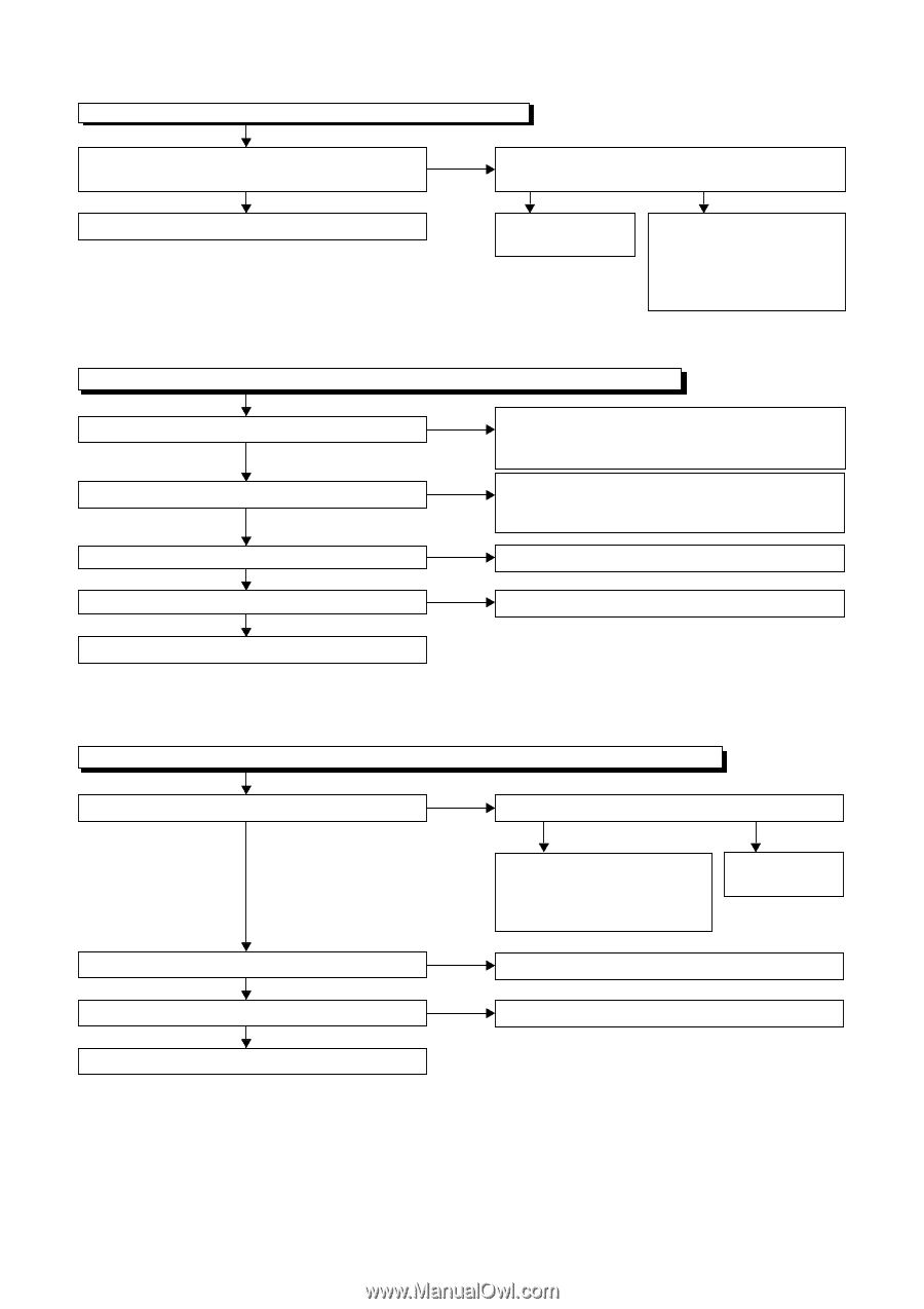
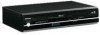
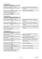
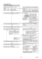
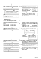
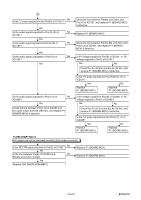
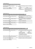
FLOW CHART NO.13 Hi-Fi audio can not be playbacked normally. (Hi-Fi E-E mode is normal.) Is the Playback Envelope signal outputted to Pin(33) of IC1451? Yes Replace 1B1 (DECK ASSEMBLY). No Is the Hi-Fi-H-SW signal inputted into to Pin(39) of IC1451? Yes No Replace P1 (BOARD MCV). Check the Hi-Fi-H-SW line between Pin(39) of IC1451 and Pin(30) of IC1501, and replace P1 (BOARD MCV) if defective. FLOW CHART NO.14 Audio can not be recorded normally in the linear audio mode. (E-E mode is normal.) No Is the audio signal inputted into Pin(76,78,80) of IC1301? Yes No Does the Bias oscillation circuit operate normally? Yes No Is the audio signal outputted to Pin(10) of IC1301? Yes No Is the audio signal outputted to Pin(9) of IC1301? Yes Replace 1B1 (DECK ASSEMBLY). Check the line between Pin(6) of IC1451 and Pin(76,78,80) of IC1301, and replace P1 (BOARD MCV) if defective. Check the Bias oscillation circuit (Q1421,Q1422, Q1425,Q1426) and replace P1 (BOARD MCV) if defective. Replace P1 (BOARD MCV). Replace P1 (BOARD MCV). FLOW CHART NO.15 Audio can not be playbacked normally in the linear audio mode. (E-E mode is normal.) Yes Is the audio signal supplied to Pin(6) of IC1301? No No Is there no dirt on the surface of ACE head assembly? Yes No Is the height of ACE head appropriate? Yes Replace 1B1 (DECK ASSEMBLY). Is the audio signal outputted to Pin(10) of IC1301? Yes No Check the line between Pin(10) of IC1301 and Pin(4) of IC1451, and replace P1 (BOARD MCV) if defective. Replace P1 (BOARD MCV). Clean the surface of ACE head assembly. Readjust the height of the ACE head assembly. 1-10-16 E9KGATR
-
 1
1 -
2
-
3
-
4
-
5
-
6
-
7
-
8
-
9
-
10
-
11
-
12
-
13
-
14
-
15
-
16
-
17
-
18
-
19
-
20
-
21
-
22
-
23
-
24
-
25
-
26
-
27
-
28
-
29
-
30
-
31
-
 32
32 -
 33
33 -
 34
34 -
 35
35 -
 36
36 -
 37
37 -
 38
38 -
 39
39 -
 40
40 -
 41
41 -
 42
42 -
43
-
44
-
45
-
46
-
47
-
48
-
49
-
50
-
51
-
52
-
53
-
54
-
55
-
56
-
57
-
58
-
59
-
60
-
61
-
62
-
63
-
64
-
65
-
66
-
67
-
68
-
69
-
70
-
71
-
72
-
73
-
74
-
75
-
76
-
77
-
78
-
79
-
80
-
81
-
82
-
83
-
84
-
85
-
86
-
87
 |
 |