Toshiba DVR610 Service Manual - Page 29
Flow Chart No.7
 |
UPC - 022265001370
View all Toshiba DVR610 manuals
Add to My Manuals
Save this manual to your list of manuals |
Page 29 highlights
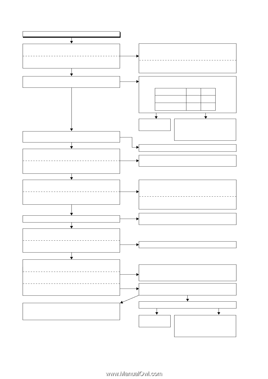
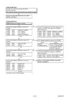
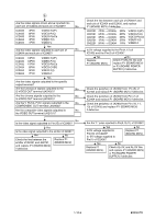
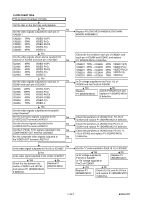
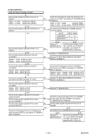
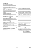
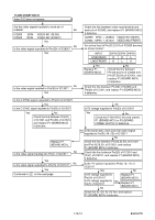
FLOW CHART NO.7 Audio E-E does not appear normally. Are the audio signals inputted to each pin of IC2801? No IC2801 4,11PIN AUDIO-IN1 (REAR) IC2801 5,14PIN AUDIO-IN2 (FRONT) Yes Are the audio signals outputted to Pin(3,13) of No IC2801? Yes Are the audio signals outputted to Pin(1,7) of No IC2803? Yes Are the audio signals outputted to each pin of CN2201? No CN2201 17PIN AUDIO (L)-OUT CN2201 15PIN AUDIO (R)-OUT Yes Are the audio signals inputted to each pin of IC2804? No IC2804 2PIN AUDIO (L)-OUT IC2804 6PIN AUDIO (R)-OUT Yes No Do Pin(18) of CN2201 become "H" level? Yes Are the audio signals outputted to each pin of IC2804? IC2804 1PIN AUDIO (L)-OUT No IC2804 7PIN AUDIO (R)-OUT Yes Are the audio signals outputted to the specific output terminal? No Are the audio signals outputted to the audio terminal (JK2805)? Are the audio signals outputted to the audio No terminal (JK2751)? Yes Check the line between Pin(4,14) of IC2406 and audio terminal (JK2751), and replace P1 (BOARD MCV) if defective. Check the line between audio input terminal and each pin of IC2801, and replace P1 (BOARD MCV) if defective. IC2801 4,11PIN → JK2804 AUDIO-IN1 (REAR) IC2801 5,14PIN → JK1232, JK1233 AUDIO-IN2 (FRONT) Are active level of Pin(9,10) of IC2801 become as shown below? INPUT 9PIN 10PIN LINE(REAR) H H LINE(FRONT) L H Yes Replace P1 (BOARD MCV). No Check the line between Pin(9, 10) of IC2801 and Pin(60,61) of IC1501, and replace P1 (BOARD MCV) if defective. Replace P1 (BOARD MCV). Replace P2 (DVD MECHANISM & DVD MAIN BOARD ASSEMBLY). Check each line between each pin of CN2201 and each pin of IC2804, and replace P1 (BOARD MCV) if defective. CN2201 17PIN → IC2804 2PIN AUDIO(L)-OUT CN2201 15PIN → IC2804 6PIN AUDIO(R)-OUT Replace P2 (DVD MECHANISM & DVD MAIN BOARD ASSEMBLY). Replace P1 (BOARD MCV). Check the periphery between Pin(1,7) of IC2804 and the audio terminal (JK2805), and replace P1 (BOARD MCV) if defective. Are the audio signals outputted to Pin(4,14) of IC2406? No Are Pin(9,10,11) of IC2406 become "L" level? Yes Replace P1 (BOARD MCV). No Check the line between Pin(9, 10, 11) of IC2406 and Pin(55) of IC1501, and replace P1 (BOARD MCV) if defective. 1-10-8 E9KGATR
-
 1
1 -
2
-
3
-
4
-
5
-
6
-
7
-
8
-
9
-
10
-
11
-
12
-
13
-
14
-
15
-
16
-
17
-
18
-
19
-
20
-
21
-
22
-
23
-
 24
24 -
 25
25 -
 26
26 -
 27
27 -
 28
28 -
 29
29 -
 30
30 -
 31
31 -
 32
32 -
 33
33 -
 34
34 -
35
-
36
-
37
-
38
-
39
-
40
-
41
-
42
-
43
-
44
-
45
-
46
-
47
-
48
-
49
-
50
-
51
-
52
-
53
-
54
-
55
-
56
-
57
-
58
-
59
-
60
-
61
-
62
-
63
-
64
-
65
-
66
-
67
-
68
-
69
-
70
-
71
-
72
-
73
-
74
-
75
-
76
-
77
-
78
-
79
-
80
-
81
-
82
-
83
-
84
-
85
-
86
-
87
 |
 |