Toshiba Satellite A110 Maintenance Manual
Toshiba Satellite A110 Manual
 |
View all Toshiba Satellite A110 manuals
Add to My Manuals
Save this manual to your list of manuals |
Toshiba Satellite A110 manual content summary:
- Toshiba Satellite A110 | Maintenance Manual - Page 1
Toshiba Personal Computer Satellite A110/Satellite Pro A110 Maintenance Manual TOSHIBA CORPORATION [CONFIDENTIAL] - Toshiba Satellite A110 | Maintenance Manual - Page 2
reviewed and validated for accuracy. The included set of instructions and descriptions are accurate for the Satellite A110/Satellite Pro A110 Series at the time of this manual's production. However, succeeding computers and manuals are subject to change without notice. Therefore, Toshiba assumes - Toshiba Satellite A110 | Maintenance Manual - Page 3
for the Toshiba Personal Computer Satellite A110/Satellite Pro A110, referred to as the Satellite A110/Satellite Pro A110 Series in this manual. The procedures described in this manual are intended to help service technicians isolate faulty Field Replaceable Units (FRUs) and replace them in - Toshiba Satellite A110 | Maintenance Manual - Page 4
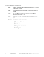
the Satellite A110/Satellite Pro A110 Series system unit and each FRU. Chapter 2 Troubleshooting Procedures explains how to diagnose and resolve FRU problems. Chapter 3 Test and Diagnostics describes how to perform test and diagnostic operations for maintenance service. Chapter 4 Replacement - Toshiba Satellite A110 | Maintenance Manual - Page 5
you are instructed to type in is shown in the boldface type below: DISKCOPY A: B: The display Text generated by the computer that appears on its display is presented in the typeface below: Format complete System transferred Satellite A110/Satellite Pro A110 Series Maintenance Manual [CONFIDENTIAL - Toshiba Satellite A110 | Maintenance Manual - Page 6
vi [CONFIDENTIAL] Satellite A110/Satellite Pro A110 Series Maintenance Manual - Toshiba Satellite A110 | Maintenance Manual - Page 7
10 Speaker Troubleshooting 2-27 2.11 Optical Drive Troubleshooting 2-29 2.11 Modem Troubleshooting 2-32 2.12 PCMCIA Troubleshooting 2-34 2.13 IEEE 1394 Troubleshooting 2-36 2.14 Wireless LAN Troubleshooting 2-38 Satellite A110/Satellite Pro A110 Series Maintenance Manual [CONFIDENTIAL] vii - Toshiba Satellite A110 | Maintenance Manual - Page 8
12 3.10 CD-ROM Test ...3-13 3.11 Keyboard Test ...3-14 3.12 Mouse (Pad) Test ...3-16 3.13 LCD Pixels Mode Test 3-18 3.14 Lid Switch Test ...3-19 3.15 HDD R/W Test ...3-20 3.16 LAN Test...3-22 3.17 RTC Test ...3-24 viii [CONFIDENTIAL] Satellite A110/Satellite Pro A110 Series Maintenance Manual - Toshiba Satellite A110 | Maintenance Manual - Page 9
Chapter 4 Replacement Procedures 4.1 General...4-1 4.2 Battery...4-7 4.3 PC Card...4-8 4.4 HDD...4-10 4.5 Modem ...4-12 4.6 Expansion Memory...4-13 4.7 Wireless LAN Unit ...4-15 4.8 Optical Drive...4-18 4.9 Keyboard...4-20 4.10 Direct Assembly...4-22 4.11 Bluetooth...4-25 4.12 Top Cover ...4-26 4.13 - Toshiba Satellite A110 | Maintenance Manual - Page 10
Module A-1 Appendix B Board Layout...B-1 Appendix C Pin Assignments C-1 Appendix D Keyboard Scan/Character Codes D-1 Appendix E Key Layout ...E-1 Appendix F Series Screw Torque List F-1 Appendix G Reliability ...G-1 x [CONFIDENTIAL] Satellite A110/Satellite Pro A110 Series Maintenance Manual - Toshiba Satellite A110 | Maintenance Manual - Page 11
Chapter 1 Hardware Overview 1 [CONFIDENTIAL] - Toshiba Satellite A110 | Maintenance Manual - Page 12
1 Hardware Overview 1-ii [CONFIDENTIAL] Detroit 20 /Detroit 20E Series Maintenance Manual - Toshiba Satellite A110 | Maintenance Manual - Page 13
1.3 2.5-inch Hard Disk Drive 1-8 1.4 Optical Device Drives 1-9 1.4.1 DVD-ROM & CD-RW 1-9 1.4.2 DVD Super Multi drive supporting ±R Double Layer 1-10 1.5 Power Supply ...1-11 1.6 Batteries ...1-13 1.6.1 Main Battery 1-14 1.6.2 RTC battery 1-15 Detroit 20 /Detroit 20E Series Maintenance Manual - Toshiba Satellite A110 | Maintenance Manual - Page 14
Hardware Overview Figures Figure 1-1 2.5-inch HDD 1-8 Tables Table 1-1 Table 1-2 Table 1-3 2.5-inch HDD specifications 1-8 DVD-ROM & CD-RW drive specifications 1-9 DVD Super Multi Double Layer drive specifications 1-10 1-iv [CONFIDENTIAL] Detroit 20 /Detroit 20E Series Maintenance Manual - Toshiba Satellite A110 | Maintenance Manual - Page 15
main memory) for ATI Radeon® XPRESS 200M • Up to 256MB shared with main memory (for more than 1G main memory) for ATI Radeon® XPRESS 200M ‰ Display • 15.4" TFT screen with a resolution of 1280 horizontal x 800 vertical pixels WXGA Detroit 20 /Detroit 20E Series Maintenance Manual [CONFIDENTIAL - Toshiba Satellite A110 | Maintenance Manual - Page 16
2 DDRII SODIMM socket for Mobile Intel® 945GM Express Chipset • Maximum upgrade to 2GB with 2 DDRII SODIMM socket for ATI RADEON® Xpress 200M Chipset ‰ BIOS • 1MB Flash ROM for system BIOS • Suspend to RAM/Disk • Password protection (Power on, HDD) • Various hot key for system control • Refreshable - Toshiba Satellite A110 | Maintenance Manual - Page 17
drivers • 12.7mm height CD-RW & DVD-ROM drive • 12.7mm height DVD Super Multi drive supporting ±R Double Layer ‰ Optional devices • DVD-ROM module • Li-Ion Battery pack • AC adapter • HDD pack ‰ Keyboard The computer's keyboard keyboard One DC-In jack • Wireless Communication Switch and WLAN indicator - Toshiba Satellite A110 | Maintenance Manual - Page 18
-D4 (MOW/ROW), WM3945ABG • Module integrated for Mini-PCI interface • Easy service for WLAN • Wireless communication killer switch (BTO) • Support MiniPCI IIIB • Support Intel Wireless Coexistence system with Taiyo Yuden V2.0 1-4 [CONFIDENTIAL] Detroit 20 /Detroit 20E Series Maintenance Manual - Toshiba Satellite A110 | Maintenance Manual - Page 19
system Windows® Operating System compatible sound system provides internal speakers as well as jacks for an external microphone and headphone. ‰ TV-out (S-Video) port Plug a 4-pin S-video cable into this connector for output of NTSC or PAL signal. Detroit 20 /Detroit 20E Series Maintenance Manual - Toshiba Satellite A110 | Maintenance Manual - Page 20
for HD CODEC ‰ Keyboard controller • ENE KB910 is use as keyboard controller and battery management unit. ‰ Memory • No on-board memory • Mobile Intel® 945GM Express Chipset with DDRII-533/667MHz • ATI Radeon® XPRESS 200M with DDRII-533MHz • Dual channel support • Easy upgrade from bottom of the - Toshiba Satellite A110 | Maintenance Manual - Page 21
1.4 Optical Device Drives ‰ Audio subsystem • Realtek ALC861 - HD audio - Stereo speakers - Sound effect by SRS software - Microphone-in and headphone-out 1 Hardware Overview Detroit 20 /Detroit 20E Series Maintenance Manual [CONFIDENTIAL] 1-7 - Toshiba Satellite A110 | Maintenance Manual - Page 22
5inch magnetic disk and mini-Winchester type magnetic heads. The computer supports hard drives up to 120 GB. The HDD is shown in Figure 1-1. Specifications are listed in Table 1-1. Figure 1-1 2.5-inch HDD Items Formatted capacity (GB) Logical Blocks (LBA) Rotational speed (rpm) Toshiba HDD Buffer - Toshiba Satellite A110 | Maintenance Manual - Page 23
DVD-RAM, DVD+R, DVD+RW, DVD+R DL, DVD-R DL. CD: CD-DA, CD-ROM Mode1, Mode2, , CD-R, CD-RW, CDROMXA Mode2 (Form1, Form2), Photo CD (single/multisession), Enhanced CD (CD-EXTRA), CD-Text Table 1-2 DVD-ROM & CD-RW drive specifications Detroit 20 /Detroit 20E Series Maintenance Manual [CONFIDENTIAL - Toshiba Satellite A110 | Maintenance Manual - Page 24
7G), DVD-RW (Ver.1.1), DVD-RAM, DVD+R, DVD+RW, DVD+R DL, DVD-R DL CD: CD-DA, CD-ROM, CD-R, CD-RW, CD-ROMXA, PhotoCD (muitiSession), Video CD, CD-Extra (CD+), CD-Text Table 1-3 DVD Super Multi Double Layer drive specifications 1-10 [CONFIDENTIAL] Detroit 20 /Detroit 20E Series Maintenance Manual - Toshiba Satellite A110 | Maintenance Manual - Page 25
= The computer is quick-charging the battery / The battery is low. ‰ Power ON/OFF sequence • When power is turned on or off, the EC starts the power on or off sequence. - SQ0-4 = power ON sequence - SQ5-B = power OFF sequence Detroit 20 /Detroit 20E Series Maintenance Manual [CONFIDENTIAL] 1-11 - Toshiba Satellite A110 | Maintenance Manual - Page 26
, the EC communicates with the E2PROM in the battery to read information of the newly installed battery. ‰ Battery capacity calculation • The EC reads battery remaining and percentage capacity from the battery through SMBus. 1-12 [CONFIDENTIAL] Detroit 20 /Detroit 20E Series Maintenance Manual - Toshiba Satellite A110 | Maintenance Manual - Page 27
) 4300mAH Main battery Lithium-Ion 10.8V(6cell) 4000mAH Main battery * Lithium-Ion 14.4V(4cell) 2000mAH RTC battery Lithium-Ion 3.0 V 15mAH * The available of this battery is dependent on the model you purchased. Detroit 20 /Detroit 20E Series Maintenance Manual [CONFIDENTIAL] 1-13 - Toshiba Satellite A110 | Maintenance Manual - Page 28
disk battery temperature is abnormal. 5. The battery SMBus communication fails. 6. The battery cell is bad. ‰ Detection of full charge A full charge is detected from the battery pack through SMBus when the battery is charging. 1-14 [CONFIDENTIAL] Detroit 20 /Detroit 20E Series Maintenance Manual - Toshiba Satellite A110 | Maintenance Manual - Page 29
the current date, time and other setup information in memory while the computer is turned off. The table below lists the charging time and data preservation period of the RTC battery. The RTC battery is charged by the adaptor or main battery, while the computer is powered on. Status Charging Time - Toshiba Satellite A110 | Maintenance Manual - Page 30
Chapter 2 Troubleshooting Procedures 2 - Toshiba Satellite A110 | Maintenance Manual - Page 31
2-19 2.8 TouchPad Troubleshooting 2-21 2.9 Speaker Troubleshooting 2-23 2.10 Optical drive troubleshooting 2-27 2.11 Modem Troubleshooting 2-30 2.12 PCMCIA Troubleshooting 2-32 2.13 IEEE 1394 Troubleshooting 2-34 2.14 Wireless LAN Troubleshooting 2-36 2-ii 2 Series Maintenance Manual - Toshiba Satellite A110 | Maintenance Manual - Page 32
drive troubleshooting process 2-27 Modem troubleshooting process 2-30 PCMCIA troubleshooting process 2-32 IEEE 1394 troubleshooting process 2-34 Wireless LAN troubleshooting process 2-36 Tables Table 2-1 Battery LED ...2-8 Table 2-2 DC-IN LED...2-9 Satellite A110 /Satellite Pro A110 Series - Toshiba Satellite A110 | Maintenance Manual - Page 33
- Toshiba Satellite A110 | Maintenance Manual - Page 34
for optical drive troubleshooting 8. Multimeter 9. External monitor 10. USB compatible keyboard 11. Multimedia sound system with line-in and line-out ports 12. Headphones 13. USB test module and USB cable 14. Music CD Satellite A110 /Satellite Pro A110 Series Maintenance Manual [CONFIDENTIAL] 2-1 - Toshiba Satellite A110 | Maintenance Manual - Page 35
enter the password. z Verify with the customer that Toshiba Windows XP is installed on the hard disk. Operating systems that were not preinstalled by Toshiba can cause the computer to malfunction. z Make sure all optional equipment is removed from the computer. z Make sure the floppy disk drive, if - Toshiba Satellite A110 | Maintenance Manual - Page 36
, type the passw ord, then press Enter. Is Toshiba W indow s being loaded? Y es A Perform diagnostics program . No R un C M 165.EX E and select the H ARD D ISK item . Figure 2-1 Troubleshooting flowchart (1/2) Satellite A110 /Satellite Pro A110 Series Maintenance Manual [CONFIDENTIAL] 2-3 - Toshiba Satellite A110 | Maintenance Manual - Page 37
Troubleshooting procedures in section 2.5 After confirming which diagnostics test has detected Yes an error, perform the appropriate procedure as outlined below. End Figure 2-1 Troubleshooting flowchart (2/2) 2-4 [CONFIDENTIAL] Satellite A110/Satellite Pro A110 Series Maintenance Manual - Toshiba Satellite A110 | Maintenance Manual - Page 38
Speaker Troubleshooting procedures in Section 2.9 and the Optical Drive Troubleshooting Procedures in Section 2.9. 6. If an error is detected by the modem test, perform the Modem Troubleshooting Procedures in Section 2.11. Satellite A110 /Satellite Pro A110 Series Maintenance Manual [CONFIDENTIAL - Toshiba Satellite A110 | Maintenance Manual - Page 39
the IEEE1394 device, perform the IEEE1394 device Troubleshooting procedures in Section 2.13. 7. If an error is detected when using the Wireless LAN, perform the Wireless LAN Troubleshooting procedures in Section 2.14. 2-6 [CONFIDENTIAL] Satellite A110/Satellite Pro A110 Series Maintenance Manual - Toshiba Satellite A110 | Maintenance Manual - Page 40
the internal power connections secure? Y es Replace system board Y es Run diagnostic program (Procedure 4) Perform internal connection No check (Procedure 5) END Figure 2-2 Power Supply Troubleshooting Process Satellite A110 /Satellite Pro A110 Series Maintenance Manual [CONFIDENTIAL] 2-7 - Toshiba Satellite A110 | Maintenance Manual - Page 41
1 second minutes remaining. The system is every 2 seconds) protected and cannot be re-powered on without the AC power connected. Amber color off Battery not in low or critical low state; It's in discharging state 2-8 [CONFIDENTIAL] Satellite A110/Satellite Pro A110 Series Maintenance Manual - Toshiba Satellite A110 | Maintenance Manual - Page 42
or may not charge the battery. Perform Check 1. Check 1 Connect a new AC adaptor. If the problem is not resolved, go to Check 2. Check 2 Insert a new battery. If the problem is still not resolved, go to Procedure 3. Satellite A110 /Satellite Pro A110 Series Maintenance Manual [CONFIDENTIAL] 2-9 - Toshiba Satellite A110 | Maintenance Manual - Page 43
battery LED does not light, go to Check 6. Check 6 Make sure the battery pack is installed in the computer correctly. If the battery is properly installed and the battery LED still does not light, go to Procedure 4. 2-10 [CONFIDENTIAL] Satellite A110/Satellite Pro A110 Series Maintenance Manual - Toshiba Satellite A110 | Maintenance Manual - Page 44
that the battery cable is firmly connected to the system board. If it is connected firmly, go to Check 3. Check 3 The system board may be damaged. Replace it with a new one following the instructions in Chapter 4. Satellite A110 /Satellite Pro A110 Series Maintenance Manual [CONFIDENTIAL] 2-11 - Toshiba Satellite A110 | Maintenance Manual - Page 45
problem detected? D isplay is not No faulty. C ontinue tro u b le sh o o tin g - refer to Figure 2.1 Y es Perform connector and replacem ent check (Procedure 3) R eplace system board END Figure 2-3 Display troubleshooting process [CONFIDENTIAL] Satellite A110/Satellite Pro A110 Series - Toshiba Satellite A110 | Maintenance Manual - Page 46
floppy disk drive, turn on the computer and run the test. Refer to Chapter 3, Tests and Diagnostics for details. If an error is detected, go to Procedure 3. If an error is not detected, the display is functioning properly. Satellite A110 /Satellite Pro A110 Series Maintenance Manual [CONFIDENTIAL - Toshiba Satellite A110 | Maintenance Manual - Page 47
problem still exists, perform Check 5. Check 5 Replace the CPU with another of the same specifications. If the problem still exists, perform Check 6. Check 6 The system board may be damaged. Replace it with a new one. 2-14 [CONFIDENTIAL] Satellite A110/Satellite Pro A110 Series Maintenance Manual - Toshiba Satellite A110 | Maintenance Manual - Page 48
problem detected? K eyboard is not No faulty. C ontinue tro u b le sh o o tin g - refer to Figure 2.1 Y es Perform connector and replacem ent check (Procedure 3) R eplace system board END Figure 2-4 Keyboard troubleshooting process Satellite A110 /Satellite Pro A110 Series Maintenance Manual - Toshiba Satellite A110 | Maintenance Manual - Page 49
it with a new one following the instructions in Chapter 4. If the problem still exists, perform Check 3. Check 3 The system board may be damaged. Replace it with a new one following the instructions in Chapter 4. 2-16 [CONFIDENTIAL] Satellite A110/Satellite Pro A110 Series Maintenance Manual - Toshiba Satellite A110 | Maintenance Manual - Page 50
port? No D oes an alternative U SB device function correctly? Y es O riginal U SB device is faulty No R eplace system board (Procedure 2) END Figure 2-5 External USB device troubleshooting process Satellite A110 /Satellite Pro A110 Series Maintenance Manual [CONFIDENTIAL] 2-17 - Toshiba Satellite A110 | Maintenance Manual - Page 51
device, the system board may be damaged. Go to Procedure 2. Procedure 2 Replace system board If the error persists, the system board may be damaged. Replace it with a new one following the instructions in Chapter 4. 2-18 [CONFIDENTIAL] Satellite A110/Satellite Pro A110 Series Maintenance Manual - Toshiba Satellite A110 | Maintenance Manual - Page 52
T V cable function properly? No Perform T V set check (Procedure 2) No R eplace T V cable T V functioning ok? Y es R eplace system board END No U se different T V set Figure 2-6 TV-out troubleshooting process Satellite A110 /Satellite Pro A110 Series Maintenance Manual [CONFIDENTIAL] 2-19 - Toshiba Satellite A110 | Maintenance Manual - Page 53
computer. If the replacement television works, the original set may be damaged. If the replacement set does not work the system board may be damaged. Replace it with a new one following the instructions in Chapter 4. 2-20 [CONFIDENTIAL] Satellite A110/Satellite Pro A110 Series Maintenance Manual - Toshiba Satellite A110 | Maintenance Manual - Page 54
Pad Troubleshooting 2.8 TouchPad Troubleshooting START 2 Troubleshooting Procedures TouchPad connection check (Procedure 1) TouchPad replacement check (Procedure 2) Replace system board END Figure 2-7 TouchPad troubleshooting process Satellite A110 /Satellite Pro A110 Series Maintenance Manual - Toshiba Satellite A110 | Maintenance Manual - Page 55
or FPC may be defective or damaged. Replace each with a new one following the steps in Chapter 4. If the FDD is still not functioning properly, replace the system board with a new one following the steps in Chapter 4. 2-22 [CONFIDENTIAL] Satellite A110/Satellite Pro A110 Series Maintenance Manual - Toshiba Satellite A110 | Maintenance Manual - Page 56
Continue troubleshooting - see Figure 2-1 Do earphones function correctly? Yes Perform connection check No (Procedure 3) Perform replacement check (Procedure 4) Replace system board END Figure 2-8 Speaker troubleshooting process Satellite A110 /Satellite Pro A110 Series Maintenance Manual - Toshiba Satellite A110 | Maintenance Manual - Page 57
speakers don't sound properly, the stereo speakers may be defective or damaged. Replace them with new ones. If the stereo speakers still do not work properly, try replacing in turn the audio board and system board. 2-24 [CONFIDENTIAL] Satellite A110/Satellite Pro A110 Series Maintenance Manual - Toshiba Satellite A110 | Maintenance Manual - Page 58
drive- No cleaning check (Procedure 2) Yes Perform software check (Procedure 3) Perform diagnostic test (Procedure 4) Perform connection and replacement check (Procedure 5) Replace system board END Figure 2-9 Optical drive troubleshooting process Satellite A110/Series Maintenance Manual - Toshiba Satellite A110 | Maintenance Manual - Page 59
4 Diagnostic test The audio test program stored in the Diagnostics Disk will test the drive's ability to play an audio CD. See Chapter 3 for details. If any errors occur while executing the diagnostic program, go to Procedure 5. 2-28 [CONFIDENTIAL] Satellite M70 Series Maintenance Manual - Toshiba Satellite A110 | Maintenance Manual - Page 60
in Chapter 4, Replacement Procedures. If the drive is still not functioning properly, perform Check 3. Check 3 The system board may be damaged. Replace it with new one following the instructions in Chapter 4, Replacement Procedures. Satellite A110/Series Maintenance Manual [CONFIDENTIAL] 2-29 - Toshiba Satellite A110 | Maintenance Manual - Page 61
check (Procedure 1) 2.11 Modem Troubleshooting Computer unable to detect telephone signal? Yes Check / replace telephone line and connections, defect disappear ? No Replace system board END Figure 2-10 Modem troubleshooting process 2-30 [CONFIDENTIAL] Satellite M70 Series Maintenance Manual - Toshiba Satellite A110 | Maintenance Manual - Page 62
2.11 Modem Troubleshooting 2 Troubleshooting Procedures This section describes how to determine if the Check 3. Check 3 The telephone cable may be damaged. Replace with a good cable. If the malfunction remains, replace the system board. Satellite A110/Series Maintenance Manual [CONFIDENTIAL] 2-31 - Toshiba Satellite A110 | Maintenance Manual - Page 63
1) 2.12 PCMCIA Troubleshooting Do errors occur during SYCARD test? PCMCIA unit is No not faulty. Yes Perform PCMCIA socket replacement check (Procedure 2) Replace system board END Figure 2-11 PCMCIA troubleshooting process 2-32 [CONFIDENTIAL] Satellite M70 Series Maintenance Manual - Toshiba Satellite A110 | Maintenance Manual - Page 64
. Disassemble the computer following the steps described in Chapter 4, Replacement Procedures and replace the socket. If the problem persists, the system board may be defective or damaged. Replace the system board with a new one following the steps in Chapter 4. Satellite A110/Series Maintenance - Toshiba Satellite A110 | Maintenance Manual - Page 65
problem detected? transmission are not No faulty. Continue troubleshooting - refer to Figure 2.1 Yes Perform connection and replacement check (Procedure 3) Replace system board END Figure 2-12 IEEE 1394 troubleshooting process 2-34 [CONFIDENTIAL] Satellite M70 Series Maintenance Manual - Toshiba Satellite A110 | Maintenance Manual - Page 66
to Check 3. Check 3 The transmission cable may be damaged. Replace with a good cable. If the malfunction persists, go to Check 4 Check 4 The system board may be damaged. Replace it with a new one following the instructions in Chapter 4. Satellite A110/Series Maintenance Manual [CONFIDENTIAL] 2-35 - Toshiba Satellite A110 | Maintenance Manual - Page 67
LAN problem delected? Yes Perform connector and replacement check (Procedure 2) Wireless LAN system No is not faulty. Continue troubleshooting - refer to Figure 2.1 Replace wireless LAN antenna/unit Replace system board END 2-36 [CONFIDENTIAL] Satellite M70 Series Maintenance Manual - Toshiba Satellite A110 | Maintenance Manual - Page 68
2.14 Wireless LAN Troubleshooting 2 Troubleshooting Procedures Figure 2-13 Wireless LAN troubleshooting process Satellite A110/Series Maintenance Manual [CONFIDENTIAL] 2-37 - Toshiba Satellite A110 | Maintenance Manual - Page 69
wireless LAN unit may be damaged. Replace it with a new one following the instructions in Chapter 4. If the problem still exists, perform Check 4. Check 4 The system board may be damaged. Replace it with a new one following the instructions in Chapter 4. 2-38 [CONFIDENTIAL] Satellite M70 Series - Toshiba Satellite A110 | Maintenance Manual - Page 70
3.1The Diagnostic Test 3. Tests and Diagnostics Chapter 3 Tests and Diagnostics 3 3-1 Satellite A110 Series Maintenance Manual - Toshiba Satellite A110 | Maintenance Manual - Page 71
Test ...3-13 3.10 Keyboard Test ...3-14 3.11 Mouse (Pad) Test ...3-17 3.12 LCD Pixels Mode Test 3-19 3.13 Magnetic switch Test ...3-20 3.14 HDD R/W Test ...3-21 3.15 LAN Test...3-23 3.16 RTC Test ...3-26 3.17 Read 1394 GUID 3-27 3.18 Button Test 3-28 3-2 Satellite A110 Series Maintenance Manual - Toshiba Satellite A110 | Maintenance Manual - Page 72
A formatted working diskette for the floppy disk drive test (Floppy Disk Drive Test) ‰ A data CD disc (ODD Test) ‰ LAN LOOPBACK (1 pcs) The following sections explain how to execute the Test & Diagnostic Program and detail the tests within the program. 3-3 Satellite A110 Series Maintenance Manual - Toshiba Satellite A110 | Maintenance Manual - Page 73
SPEAKER AUDIO TEST D. FAN ON/OFF TEST E. MAIN BATTERY CHARGE TEST F. FDD TEST G. ODD TEST H. KEYBOARD TEST I. MOUSE (PAD) TEST J. LCD PIXELS MODE TEST K. MAGNETIC SWITCH TEST L. HDD R/W TEST M. LAN TEST N. RTC TEST O. IEEE1394 CODE TEST P. Button test 3-4 Satellite A110 Series Maintenance Manual - Toshiba Satellite A110 | Maintenance Manual - Page 74
3.2 Executing the Diagnostic Test 3. Tests and Diagnostics The below display will show up at the beginning of T&D program If the test result passes, the following display will show up: 3-5 Satellite A110 Series Maintenance Manual - Toshiba Satellite A110 | Maintenance Manual - Page 75
key for next actions - the below display presented if copying test log file onto diskette is necessary. This action will be executed when "Y" key pressed. 3-6 Satellite A110 Series Maintenance Manual - Toshiba Satellite A110 | Maintenance Manual - Page 76
it's necessary to leave this program. Program will quit when "Y" key pressed and it will go back main menu for next test if "N" key pressed. 3-7 Satellite A110 Series Maintenance Manual - Toshiba Satellite A110 | Maintenance Manual - Page 77
Š ODD TYPE ((DVD-SuperMulti; COMBO; ...) Š Panel ID Š HDD type & capacity (Vendor ID. Model .Firmware) Š VRAM size / VGA CHIP TYPE Š Battery cell (6cell;9cell;12cell) Š Wireless type Š 1394 Š SKU ID Š Part - Number The screen should display as below: 3-8 Satellite A110 Series Maintenance Manual - Toshiba Satellite A110 | Maintenance Manual - Page 78
DMI information and makes comparison with Part - Number data. NOTE: To execute this test, you must input unit Part Number as "Uppercase Character". The screen should display as below, indicating whether the test is passed or failed after comparison. 3-9 Satellite A110 Series Maintenance Manual - Toshiba Satellite A110 | Maintenance Manual - Page 79
both speakers if they are OK within 3 times "Beep" sound generated. NOTE: Remember to tune up the volume as "Maximum" before this test starts. The screen should display as below, indicating whether the test is passed or failed after the question. 3-10 Satellite A110 Series Maintenance Manual - Toshiba Satellite A110 | Maintenance Manual - Page 80
sound. The screen should display as below, indicating whether the test is passed or failed after the question. 3.7 Main Battery Charge Test NOTE: The AC adaptor (65W, 19V) should be connected to successfully run this test. This test shows and measures the main battery: 3-11 Satellite A110 Series - Toshiba Satellite A110 | Maintenance Manual - Page 81
diskette (1.44 MB). Remove the diagnostics diskette and insert the work diskette into the FDD. The contents of the floppy diskette maybe erased. The Floppy Disk Test includes three subtests of the: 3-12 Satellite A110 Series Maintenance Manual - Toshiba Satellite A110 | Maintenance Manual - Page 82
. NOTE: Press "Esc" key can skip the current subtest. The screen should display as below, indicating whether the subtests pass or fail when finished must be inserted into the ODD drive before this test starts. The ODD test includes two subtests of the: 3-13 Satellite A110 Series Maintenance Manual - Toshiba Satellite A110 | Maintenance Manual - Page 83
keys function. NOTE: The Num Lock and the Overlay mode must be off to execute the keyboard test. Before keyboard test starts, the keyboard matrix code should be chosen as below display: 1. K (UK, for Europe) 2. S (US, for America) 3. J (JPN for Japan) 3-14 Satellite A110 Series Maintenance Manual - Toshiba Satellite A110 | Maintenance Manual - Page 84
after the question. NOTE: The "Fn" key cannot be tested in the keyboard test. To determine whether the "Fn" key is working correctly, press "Fn+F6 " or "Fn+F7 " keys to check if LCD display brightness change gradually. * Fn+F6 = Fn+Up , Fn+F7 = Fn+Down 3-15 Satellite A110 Series Maintenance Manual - Toshiba Satellite A110 | Maintenance Manual - Page 85
3. Tests and Diagnostics 3.10 Keyboard Test 3-16 Satellite A110 Series Maintenance Manual - Toshiba Satellite A110 | Maintenance Manual - Page 86
Touch Pad buttons. If the buttons are clicked, the cursors should appear in the corresponding box of the button figure that is displayed on the screen as below. 3-17 Satellite A110 Series Maintenance Manual - Toshiba Satellite A110 | Maintenance Manual - Page 87
the Touch Pad installed may only have two buttons. In this case, the central compartment in the figure does not correspond to any button. 3-18 Satellite A110 Series Maintenance Manual - Toshiba Satellite A110 | Maintenance Manual - Page 88
/256 colors), 640*200 (2/16 colors), 640*350 (2/16 colors), 640*480 (2/16/256 colors), 800*600 (256 colors) and 1024*768 (256 colors). The screen should display as below, indicating whether the test is passed or failed after the question. 3-19 Satellite A110 Series Maintenance Manual - Toshiba Satellite A110 | Maintenance Manual - Page 89
of the unit. When LCD cover closed, the lid should enable to turn off the display. NOTE: Remember to tune up the volume as "Maximum "Beep" sound happened during LCD closed. 3. Open the LCD. Then it will indicate whether the test is passed or failed. 3-20 Satellite A110 Series Maintenance Manual - Toshiba Satellite A110 | Maintenance Manual - Page 90
to input password - "hard disk" before HDD test starts. After the choice HDD test, Screen would display as below: If input password is Right, the screen would display as below: Press any key to test HDD function, the screen would display as below: 3-21 Satellite A110 Series Maintenance Manual - Toshiba Satellite A110 | Maintenance Manual - Page 91
If input password is wrong, the screen would display as below: The screen should display as previous picture, indicating whether the subtest is passed or failed when finished. NOTE: The AC adaptor should be connected to successfully run this test. 3-22 Satellite A110 Series Maintenance Manual - Toshiba Satellite A110 | Maintenance Manual - Page 92
to plug in before test begins. And LAN information will show on the test screen: Š IO Base - Port: A000H Š IRQ - BH, it's "IRQ - 1514 Bytes. Š Line Speed - 100Mbps or 10 Mbps. Š Bus ID - it's "4". 3. Tests and Diagnostics The LAN test includes two Satellite A110 Series Maintenance Manual - Toshiba Satellite A110 | Maintenance Manual - Page 93
3. Tests and Diagnostics 3.15 LAN Test The screen should display as below, indicating whether the subtests pass or fail when finished. 3-24 Satellite A110 Series Maintenance Manual - Toshiba Satellite A110 | Maintenance Manual - Page 94
3.15 LAN Test 3. Tests and Diagnostics If an error is detected and a test fails, the following message displays: 3-25 Satellite A110 Series Maintenance Manual - Toshiba Satellite A110 | Maintenance Manual - Page 95
3.16 RTC Test Checks the computer's RTC (Real Time Clock) and calendar functions by comparing the DOS and CMOS values. The test runs automatically. The screen should display as below, indicating whether the test is passed or failed when finished. 3-26 Satellite A110 Series Maintenance Manual - Toshiba Satellite A110 | Maintenance Manual - Page 96
GUID 3. Tests and Diagnostics 3.17 Read 1394 GUID This test will check if the computer's EEPROM 1394GUID code is correct. NOTE: Must open the RAM Door to see RAM connector GUID bar code before test item begins. The figure below will be displayed: 3-27 Satellite A110 Series Maintenance Manual - Toshiba Satellite A110 | Maintenance Manual - Page 97
: 1. 1 (1 button) 2. 2 (6 button) When you execute this test, the button test choice show on the display. When any key is pressed, The corresponding key on the screen changes to black as shown below. 3-28 Satellite A110 Series Maintenance Manual - Toshiba Satellite A110 | Maintenance Manual - Page 98
test allows the user to manually test each of the five CD control buttons. Key"WWW" need to press first. One will hear one "bi" sound when press"WWW" or "Audio" Sound and continuously "bi" sound for another key test. The figure below will be displayed: 3-29 Satellite A110 Series Maintenance Manual - Toshiba Satellite A110 | Maintenance Manual - Page 99
3.18 Button Test 3. Tests and Diagnostics Press each of the buttons on the front panel in turn. A yellow bar will appear on the relevant section of the figure if the button passes the test. Press Ctrl +C to quit the test. 3-30 Satellite A110 Series Maintenance Manual - Toshiba Satellite A110 | Maintenance Manual - Page 100
4 Chapter 4 Replacement Procedures [CONFIDENTIAL] - Toshiba Satellite A110 | Maintenance Manual - Page 101
4 Replacement Procedures 4-ii [CONFIDENTIAL] Detroit 20 /Detroit 20E Series Maintenance Manual - Toshiba Satellite A110 | Maintenance Manual - Page 102
4 Replacement Procedures Chapter 4 Contents 4.1 General...4-1 4.2 Battery...4-7 4.3 PC Card...4-8 4.4 HDD...4-10 4.5 Modem ...4-12 4.6 Expansion Memory 4-13 4.7 Wireless LAN Unit 4-15 4.8 Optical Drive...4-18 4.9 Keyboard...4-20 4.10 Display Assembly ...4-22 4.11 Bluetooth...4-25 4.12 Top Cover - Toshiba Satellite A110 | Maintenance Manual - Page 103
4-31 Removing the battery pack 4-7 Pressing wireless LAN card 4-16 Removing the optical drive screw 4-18 Removing the optical drive 4-18 Removing the optical drive bracket 4-19 Removing the strip cover 4-20 Removing the keyboard screws 4-20 Disconnecting the keyboard Series Maintenance Manual - Toshiba Satellite A110 | Maintenance Manual - Page 104
CPU 4-33 Disconnecting the fan wire 4-33 Removing the fan screws 4-34 Removing the display mask screws 4-35 Removing the LCD module screws 4-36 Removing the connectors 4-36 Removing the bracket screws 4-37 Removing the FL inverter board 4-38 Detroit 20 /Detroit 20E Series Maintenance Manual - Toshiba Satellite A110 | Maintenance Manual - Page 105
4 Replacement Procedures 4-vi [CONFIDENTIAL] Detroit 20 /Detroit 20E Series Maintenance Manual - Toshiba Satellite A110 | Maintenance Manual - Page 106
HDD and/or Modem Battery pack ODD and Expansion Memory Module Keyboard Bluetooth Top Cover System Board Fan & Thermal Module CPU Speakers TouchPad Wireless LAN Display Assembly Display Mask LCD Module FL Inverter Board Detroit 20 /Detroit 20E Series Maintenance Manual [CONFIDENTIAL] 4-1 - Toshiba Satellite A110 | Maintenance Manual - Page 107
keyboard and display assembly in turn overlap the top cover. Always starts the disassembly process by removing the battery pack. HDD and/or Modem Battery pack ODD and Expansion Memory Module Keyboard Bluetooth Top Cover System Board Fan & Thermal Module CPU Speakers TouchPad Wireless - Toshiba Satellite A110 | Maintenance Manual - Page 108
all cables and connectors are securely fastened. CAUTION: To avoid damage to the computer 1. When you change a component, be sure the replacement component meets the required specifications. Never use foreign parts. 2. Metal objects such as screws or paper clips which fall into the unit can cause - Toshiba Satellite A110 | Maintenance Manual - Page 109
FRU you are replacing is causing the abnormal operation by performing the necessary troubleshooting and diagnostics tests described in chapters 2 and 3 of this manual. 5. Do not perform any operations that are not necessary and use only the described procedures for disassembling and installing FRUs - Toshiba Satellite A110 | Maintenance Manual - Page 110
Replacement Procedures Disassembly follow the instructions closely. Most problems arise when you are assembling the computer in a hurry. ‰ Make sure all cables and connectors are securely fastened. ‰ Before securing the FRU or other parts Series Maintenance Manual [CONFIDENTIAL] 4-5 - Toshiba Satellite A110 | Maintenance Manual - Page 111
cost for damaged or destroyed parts. The following equipment is necessary to disassemble and reassemble the computer: ‰ One M2 Phillips screwdriver to remove and replace screws. ‰ One T8 security in highly static sensitive areas. 4-6 [CONFIDENTIAL] Detroit 20 /Detroit 20E Series Maintenance Manual - Toshiba Satellite A110 | Maintenance Manual - Page 112
ion battery and can explode if not properly replaced, used, handled or disposed of. Use only batteries recommended by Toshiba as replacements. 1. Slide the battery pack into the battery bay. The battery bay latch clicks into place automatically. Detroit 20 /Detroit 20E Series Maintenance Manual - Toshiba Satellite A110 | Maintenance Manual - Page 113
4 Replacement Procedures 4.3 PC Card Removing a PC Card To remove a PC Card, follow the steps below: 1. Click the Safely Remove Hardware icon 5. Grasp the PC Card and remove it. 4.3 PC Card Figure 4-2 Pressing the eject button 4-8 [CONFIDENTIAL] Detroit 20 /Detroit 20E Series Maintenance Manual - Toshiba Satellite A110 | Maintenance Manual - Page 114
4.3 PC Card Installing the PC Card To install the PC Card, follow the steps below: 1. Insert the PC Card. 2. Press gently to ensure a firm connection. 4 Replacement Procedures Figure 4-3 Installing the PC card Detroit 20 /Detroit 20E Series Maintenance Manual [CONFIDENTIAL] 4-9 - Toshiba Satellite A110 | Maintenance Manual - Page 115
Replacement Procedures 4.4 HDD 4.4 HDD CAUTION: When handling the HDD, do not press the top surface as shown by the arrow. Hold it by the sides. Figure 4-4 HDD Removing the HDD Module Follow the steps below to remove HDD module: 1. Turn ] Detroit 20 /Detroit 20E Series Maintenance Manual - Toshiba Satellite A110 | Maintenance Manual - Page 116
4.4 HDD 4 Replacement Procedures 5. Remove four black M3x3 screws that secure the EMI Shielding to the HDD. Figure 4-6 Removing the EMI black M2.5x3 screws. 4. Secure the HDD door with three black M2.5x4 safety screws. Detroit 20 /Detroit 20E Series Maintenance Manual [CONFIDENTIAL] 4-11 - Toshiba Satellite A110 | Maintenance Manual - Page 117
4 Replacement Procedures 4.5 Modem 4.5 Modem Removing the Modem To remove the modem, you need to remove the HDD door first, described in the . 2. Fit the modem onto its connector and secure it with one black M2.5x3 screw. 4-12 [CONFIDENTIAL] Detroit 20 /Detroit 20E Series Maintenance Manual - Toshiba Satellite A110 | Maintenance Manual - Page 118
(C). 4. Seat the cover and secure its screw. Figure 4-8 Removing the expansion memory CAUTION: Do not touch the connectors on the expansion memory or on the computer. Debris on the connectors may cause memory access problems. Detroit 20 /Detroit 20E Series Maintenance Manual [CONFIDENTIAL] 4-13 - Toshiba Satellite A110 | Maintenance Manual - Page 119
4 Replacement Procedures 4.6 Expansion Memory Installing the Expansion Memory CAUTION: Do not touch the connectors on the expansion memory or on the computer. Debris on the connectors may cause memory access problems. To install a memory module, follow the steps below and refer to the figures in - Toshiba Satellite A110 | Maintenance Manual - Page 120
black M2x4 screw securing the wireless LAN door, and then remove it. Figure 4-10 Removing the wireless LAN door 2. Disconnect the antenna wires from the wireless LAN module. Figure 4-11 Removing the wireless LAN antenna wires Detroit 20 /Detroit 20E Series Maintenance Manual [CONFIDENTIAL] 4-15 - Toshiba Satellite A110 | Maintenance Manual - Page 121
4. Grasp the wireless LAN unit and pull it out. Figure 4-13 Removing the wireless LAN card CAUTION: Do not touch the connectors on the wireless LAN unit or on the computer. Debris on the connectors may cause malfunction. 4-16 [CONFIDENTIAL] Detroit 20 /Detroit 20E Series Maintenance Manual - Toshiba Satellite A110 | Maintenance Manual - Page 122
press down. Secure the wireless LAN unit with two M2.5x4 screws. 4. Attach the white antenna to the main connector, and the black antenna to the Aux connector. 5. Use the black M2.5x4 screw to secure the wireless LAN door. Detroit 20 /Detroit 20E Series Maintenance Manual [CONFIDENTIAL] 4-17 - Toshiba Satellite A110 | Maintenance Manual - Page 123
4 Replacement Procedures 4.8 Optical Drive This computer may be fitted with a: CD-RW/DVD-ROM drive DVD Super Multi drive Disassembling the Optical Drive To disassemble the optical drive, follow the steps below: 1. Remove the black M2.5x3 screw securing the optical drive. 4.8 Optical Drive - Toshiba Satellite A110 | Maintenance Manual - Page 124
drive bracket plate to the rear panel of optical drive. 2. Secure the optical drive bracket plate with two black M2x3 screws. 3. Install the optical drive into the bay and use the black M2.5x3 screw to secure the optical drive. Detroit 20 /Detroit 20E Series Maintenance Manual [CONFIDENTIAL - Toshiba Satellite A110 | Maintenance Manual - Page 125
the strip cover and keyboard to lever the strip cover up and then release the strip cover. Figure 4-17 Removing the strip cover 3. Remove two black M2x3 screws securing the keyboard. Figure 4-18 Removing the keyboard screws 4-20 [CONFIDENTIAL] Detroit 20 /Detroit 20E Series Maintenance Manual - Toshiba Satellite A110 | Maintenance Manual - Page 126
section. 1. Connect the keyboard FPC cable to the system board. 2. Set the keyboard in place and secure it with two black M2x3 screws. 3. Set the strip cover in place and press down to secure the strip cover latches engage. Detroit 20 /Detroit 20E Series Maintenance Manual [CONFIDENTIAL] 4-21 - Toshiba Satellite A110 | Maintenance Manual - Page 127
4 Replacement Procedures 4.10 Display Assembly 4.10 Display Assembly Removing the Display Assembly To remove the display assembly, first remove the keyboard and wireless LAN, then follow the steps below: 1. Disconnect the LCD power cable from the top chassis. Figure 4-20 Disconnecting the LCD - Toshiba Satellite A110 | Maintenance Manual - Page 128
the wireless LAN antennas. 4 Replacement Procedures Figure 4-22 Pulling out the wireless LAN antennas 4. Turn the computer upside down and remove two M2.5x12 screws securing the LCD. Figure 4-23 Removing the screws from the bottom of the computer Detroit 20 /Detroit 20E Series Maintenance Manual - Toshiba Satellite A110 | Maintenance Manual - Page 129
hinge on the topside. 3. Secure two M2.5x12 black screws to the computer's backside. 4. Connect the LCD power cable to the top chassis. 5. Thread the wireless LAN antennas back into their hole. 6. Replace the keyboard door. 4-24 [CONFIDENTIAL] Detroit 20 /Detroit 20E Series Maintenance Manual - Toshiba Satellite A110 | Maintenance Manual - Page 130
4.11 Bluetooth 4 Replacement Procedures 4.11 Bluetooth Removing the Bluetooth module To remove the Bluetooth module, first remove the keyboard as described in the preceding section and antenna wire to the antenna connector. Detroit 20 /Detroit 20E Series Maintenance Manual [CONFIDENTIAL] 4-25 - Toshiba Satellite A110 | Maintenance Manual - Page 131
Replacement Procedures 4.12 Top Cover 4.12 Top Cover Removing the Cover To remove the top cover, first remove the battery pack, keyboard, display assembly, optical drive, HDD, memory module, and wireless Removing the cables 4-26 [CONFIDENTIAL] Detroit 20 /Detroit 20E Series Maintenance Manual - Toshiba Satellite A110 | Maintenance Manual - Page 132
Replacement Procedures 3. Turn the computer upside down and remove eleven M2.5x12, three M2.5x8, and one silver M2.5x3 screws securing the bottom cover to the top cover. Figure 4-28 Removing the top cover (back panel screws) 4. Turn M2.5x3 screw. 3. Turn the computer upside down and secure eleven M2 - Toshiba Satellite A110 | Maintenance Manual - Page 133
4 Replacement Procedures 4.13 TouchPad 4.13 TouchPad Removing the TouchPad To remove the TouchPad, first remove the top cover, then follow the with two black M2.5x3 screws. 4. Connect the TouchPad FFC cables to the TouchPad. 4-28 [CONFIDENTIAL] Detroit 20 /Detroit 20E Series Maintenance Manual - Toshiba Satellite A110 | Maintenance Manual - Page 134
4.14 System Board 4 Replacement Procedures 4.14 System Board Removing the System Board To remove the system board, first remove the top cover, from the back of the system board. Figure 4-31 Removing the hexagonal screws Detroit 20 /Detroit 20E Series Maintenance Manual [CONFIDENTIAL] 4-29 - Toshiba Satellite A110 | Maintenance Manual - Page 135
4 Replacement Procedures 4. Disconnect the speaker cable. 4.14 System Board Figure 4-32 Removing the speaker cable 5. Lift out the system board. board. 4. Seat the Express PC Board and Express Bracket and secure their screws. 4-30 [CONFIDENTIAL] Detroit 20 /Detroit 20E Series Maintenance Manual - Toshiba Satellite A110 | Maintenance Manual - Page 136
4.15 Speakers 4 Replacement Procedures 4.15 Speakers Removing the Speakers To remove the speakers, first remove the top cover, system board and with two M2.5x3 screws. 3. Secure the right speaker with two M2.5x3 screws. Detroit 20 /Detroit 20E Series Maintenance Manual [CONFIDENTIAL] 4-31 - Toshiba Satellite A110 | Maintenance Manual - Page 137
To install the thermal module, follow the steps below and refer to the figures in the preceding section. 1. Restore the thermal grease to the top of the CPU. 2. Seat the thermal module, then secure it with four M2.5x3 screws. 4-32 [CONFIDENTIAL] Detroit 20 /Detroit 20E Series Maintenance Manual - Toshiba Satellite A110 | Maintenance Manual - Page 138
the CPU by turning the marked cam to disengage the mechanism that locks the CPU in place and then lifting it out. Figure 4-35 Removing the CPU 2. Disconnect the fan wire from the system board. Figure 4-36 Disconnecting the fan wire Detroit 20 /Detroit 20E Series Maintenance Manual [CONFIDENTIAL - Toshiba Satellite A110 | Maintenance Manual - Page 139
5x6 fan screws on the bottom of the system board. 2. Connect the fan wire to the system board. 3. Reinstall the CPU, ensuring that you restore the thermal grease on its surface and then turn the cam back to the locked position. 4-34 [CONFIDENTIAL] Detroit 20 /Detroit 20E Series Maintenance Manual - Toshiba Satellite A110 | Maintenance Manual - Page 140
4.18 Display Mask 4 Replacement Procedures 4.18 Display Mask Removing the Display Mask To remove the display mask, first remove the display the snaps on each side. 2. Secure the display mask with four black M2.5x6 screws. Detroit 20 /Detroit 20E Series Maintenance Manual [CONFIDENTIAL] 4-35 - Toshiba Satellite A110 | Maintenance Manual - Page 141
4 Replacement Procedures 4.19 LCD Module 4.19 LCD Module Removing the LCD Module To remove the LCD module, first remove the display two connectors on either side of the FL inverter board. Figure 4-40 Removing the connectors 4-36 [CONFIDENTIAL] Detroit 20 /Detroit 20E Series Maintenance Manual - Toshiba Satellite A110 | Maintenance Manual - Page 142
the bracket screws NOTE: If the LCD module malfunctions, remove the LCD cable and LCD bracket. Then replace the whole LCD module unit. Installing the LCD Module To install the LCD module, follow the steps LCD cable in place. Detroit 20 /Detroit 20E Series Maintenance Manual [CONFIDENTIAL] 4-37 - Toshiba Satellite A110 | Maintenance Manual - Page 143
4 Replacement Procedures 4.20 FL Inverter Board 4.20 FL Inverter Board Removing the FL Inverter Board To remove the FL inverter board, first remove the battery pack, the display assembly, display mask, the computer. 4-38 [CONFIDENTIAL] Detroit 20 /Detroit 20E Series Maintenance Manual
-
 1
1 -
 2
2 -
 3
3 -
 4
4 -
 5
5 -
 6
6 -
 7
7 -
8
-
9
-
10
-
11
-
12
-
13
-
14
-
15
-
16
-
17
-
18
-
19
-
20
-
21
-
22
-
23
-
24
-
25
-
26
-
27
-
28
-
29
-
30
-
31
-
32
-
33
-
34
-
35
-
36
-
37
-
38
-
39
-
40
-
41
-
42
-
43
-
44
-
45
-
46
-
47
-
48
-
49
-
50
-
51
-
52
-
53
-
54
-
55
-
56
-
57
-
58
-
59
-
60
-
61
-
62
-
63
-
64
-
65
-
66
-
67
-
68
-
69
-
70
-
71
-
72
-
73
-
74
-
75
-
76
-
77
-
78
-
79
-
80
-
81
-
82
-
83
-
84
-
85
-
86
-
87
-
88
-
89
-
90
-
91
-
92
-
93
-
94
-
95
-
96
-
97
-
98
-
99
-
100
-
101
-
102
-
103
-
104
-
105
-
106
-
107
-
108
-
109
-
110
-
111
-
112
-
113
-
114
-
115
-
116
-
117
-
118
-
119
-
120
-
121
-
122
-
123
-
124
-
125
-
126
-
127
-
128
-
129
-
130
-
131
-
132
-
133
-
134
-
135
-
136
-
137
-
138
-
139
-
140
-
141
-
142
-
143
 |
 |

Toshiba Personal Computer
Satellite A110/Satellite Pro A110
Maintenance Manual
TOSHIBA CORPORATION
[CONFIDENTIAL]