Toshiba Satellite A110 Maintenance Manual - Page 131
Top Cover, Removing the Cover
 |
View all Toshiba Satellite A110 manuals
Add to My Manuals
Save this manual to your list of manuals |
Page 131 highlights
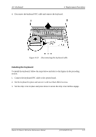
4 Replacement Procedures 4.12 Top Cover 4.12 Top Cover Removing the Cover To remove the top cover, first remove the battery pack, keyboard, display assembly, optical drive, HDD, memory module, and wireless LAN as described in the preceding sections, then follow the steps below: 1. Remove one silver M2.5x13 screw, two M2.5x6 screws, and one M2.5x3 screw securing top cover. Figure 4-26 Removing the top cover (front panel screws) 2. Detach the Power Switch FFC cable and TouchPad FFC cable on the top chassis. Figure 4-27 Removing the cables 4-26 [CONFIDENTIAL] Detroit 20 /Detroit 20E Series Maintenance Manual
-
 1
1 -
2
-
3
-
4
-
5
-
6
-
7
-
8
-
9
-
10
-
11
-
12
-
13
-
14
-
15
-
16
-
17
-
18
-
19
-
20
-
21
-
22
-
23
-
24
-
25
-
26
-
27
-
28
-
29
-
30
-
31
-
32
-
33
-
34
-
35
-
36
-
37
-
38
-
39
-
40
-
41
-
42
-
43
-
44
-
45
-
46
-
47
-
48
-
49
-
50
-
51
-
52
-
53
-
54
-
55
-
56
-
57
-
58
-
59
-
60
-
61
-
62
-
63
-
64
-
65
-
66
-
67
-
68
-
69
-
70
-
71
-
72
-
73
-
74
-
75
-
76
-
77
-
78
-
79
-
80
-
81
-
82
-
83
-
84
-
85
-
86
-
87
-
88
-
89
-
90
-
91
-
92
-
93
-
94
-
95
-
96
-
97
-
98
-
99
-
100
-
101
-
102
-
103
-
104
-
105
-
106
-
107
-
108
-
109
-
110
-
111
-
112
-
113
-
114
-
115
-
116
-
117
-
118
-
119
-
120
-
121
-
122
-
123
-
124
-
125
-
 126
126 -
 127
127 -
 128
128 -
 129
129 -
 130
130 -
 131
131 -
 132
132 -
 133
133 -
 134
134 -
 135
135 -
 136
136 -
137
-
138
-
139
-
140
-
141
-
142
-
143
 |
 |

4
Replacement Procedures
4.12
Top Cover
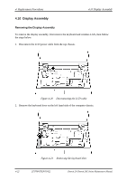
4.12 Top Cover
Removing the Cover
To remove the top cover, first remove the battery pack, keyboard, display assembly, optical
drive, HDD, memory module, and wireless LAN as described in the preceding sections, then
follow the steps below:
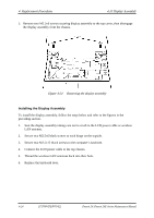
1.
Remove one silver M2.5x13 screw, two M2.5x6 screws, and one M2.5x3 screw securing
top cover.
Figure 4-26
Removing the top cover (front panel screws)
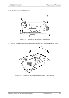
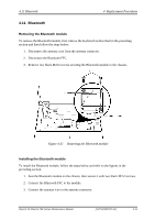
2.
Detach the Power Switch FFC cable and TouchPad FFC cable on the top chassis.
Figure 4-27
Removing the cables
4-26
[CONFIDENTIAL]
Detroit 20 /Detroit 20E Series Maintenance Manual