Toshiba TDP-TW300U Owners Manual - Page 10
Parts on the rear panel, Label locations
 |
View all Toshiba TDP-TW300U manuals
Add to My Manuals
Save this manual to your list of manuals |
Page 10 highlights
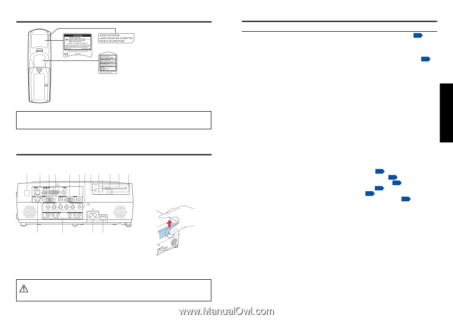
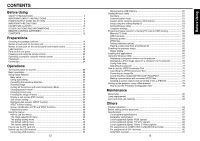
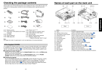
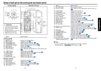
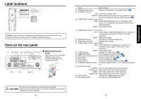
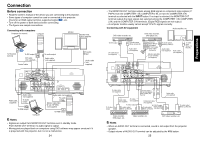
Label locations Caution - use of controls or adjustments or performance of procedures other than those specified herein may result in hazardous radiation exposure. Parts on the rear panel (1) (2) (3)(4) (5) (6)(7)(8) (9) (11)(12) (13) (10) ■ Removing the slot cover Press on the circle ("O") while sliding the cover in the direction of the arrow. The cover will come off. (14) (15) (16) (17) Do not carry the projector by having the slot cover part. CAUTION Doing so may cause that cover to come off, resulting in the projector malfunction, injury or damage. 18 Name : Main Function (1) Infrared remote sensor : Senses commands from the remote control. p.20 (2) CONTROL terminal LAN : Connects a network cable. RS232C : When operating the projector via a computer, connect this to the controlling computer's RS-232C port. p.89 (3) COMPUTER (Y/PB/PR) 2 IN terminal RGB : Input analog RGB signal from a computer or other source, or a component video signal (Y/PB/PR) from video equipment. AUDIO : Input audio signals. (4) COMPUTER (Y/PB/PR) 1 IN terminal DVI-I : Input analog or digital RGB signal from a computer, or a component video signal (Y/PB/PR) from video equipment. AUDIO : Input audio signals. (5) MONITOR terminal : Connect to a computer display, etc. (6) AUDIO OUT terminal : Outputs audio signals. (7) COMPUTER (Y/PB/PR) 3 IN terminal BNC : Input G/B/R/HD/VD signal from a computer, or a component video signal (Y/PB/PR) from video equipment. AUDIO : Input audio signals. (8) CARD indicator : Displays PC card's status. p.23 (9) UNMOUNT button : Press before removing PC card. p.23 (10) RESET switch (inside depression) : Press if CARD indicator turns red. p.23 (11) Eject button : Press to remove PC card. p.23 (12) PC card slot : Insert PC cards here. p.23 (13) USB terminal : Connects a commercial USB memory. p.21 (14) CAMERA POWER terminal : DC power supply terminal (+15 V). Reserved for future use. (15) VIDEO IN terminal S-VIDEO : Input S video signals from video equipment. AUDIO (L/R) : Input audio signals from video equipment. VIDEO : Input video signals from video equipment. AUDIO (L/R) : Input audio signals from video equipment. (16) AC IN socket : Connect the supplied power cord here. (17) Main power switch : AC power line ON (standby)/OFF. 19 Preparations
-
 1
1 -
2
-
3
-
4
-
 5
5 -
 6
6 -
 7
7 -
 8
8 -
 9
9 -
 10
10 -
 11
11 -
 12
12 -
 13
13 -
 14
14 -
 15
15 -
16
-
17
-
18
-
19
-
20
-
21
-
22
-
23
-
24
-
25
-
26
-
27
-
28
-
29
-
30
-
31
-
32
-
33
-
34
-
35
-
36
-
37
-
38
-
39
-
40
-
41
-
42
-
43
-
44
-
45
-
46
-
47
 |
 |