Toshiba Tecra M9 PTM91C-TG509C Users Manual Canada; English - Page 43
Ultra Slim Bay lock, Hardware, Utilities and Options, Additional memory module
 |
View all Toshiba Tecra M9 PTM91C-TG509C manuals
Add to My Manuals
Save this manual to your list of manuals |
Page 43 highlights
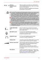
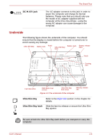
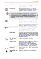
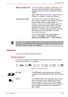
The Grand Tour Notches Docking port Notches on the computer engage hooks on the TOSHIBA Express Port Replicator to ensure a secure connection. This port enables connection of an optional TOSHIBA Express Port Replicator described in Chapter 3, Hardware, Utilities and Options. ■ Only the TOSHIBA Express Port Replicator can be used with this computer. Do not attempt to use any other Port Replicator. ■ Keep foreign objects out of the docking port. A pin or similar object can damage the computer's circuitry. A plastic shutter protects the connector. Memory module slot The slot B memory module is located here. The memory module slot allows for the installation, replacement and removal of additional memory module. Refer to the Additional memory module section in Chapter 3, Hardware, Utilities and Options. Battery release latch Slide and hold this latch into its 'Unlock' position in order to release the battery pack ready for removal. For more detailed information on removing the battery pack please refer to Chapter 6, Power and Power-Up Modes. Battery pack The battery pack provides power to the computer when the AC adaptor is not connected. For more detailed information on the use and operation of the battery pack please refer to Chapter 6, Power and Power-Up Modes. HDD pack cover screws Two screws secures the HDD cover. Hard disk drive Battery lock This contains a Hard disk drive pack, which can be removed and reinstalled. For more information on how to remove or reinstall the Hard disk drive pack, refer to the section on the in Chapter 3, Hardware, Utilities and Options. Slide the battery lock to release the battery pack for removal. Ultra Slim Bay lock One screw secures the Ultra Slim Bay latch. screw User's Manual 2-7
-
 1
1 -
2
-
3
-
4
-
5
-
6
-
7
-
8
-
9
-
10
-
11
-
12
-
13
-
14
-
15
-
16
-
17
-
18
-
19
-
20
-
21
-
22
-
23
-
24
-
25
-
26
-
27
-
28
-
29
-
30
-
31
-
32
-
33
-
34
-
35
-
36
-
37
-
 38
38 -
 39
39 -
 40
40 -
 41
41 -
 42
42 -
 43
43 -
 44
44 -
 45
45 -
 46
46 -
 47
47 -
 48
48 -
49
-
50
-
51
-
52
-
53
-
54
-
55
-
56
-
57
-
58
-
59
-
60
-
61
-
62
-
63
-
64
-
65
-
66
-
67
-
68
-
69
-
70
-
71
-
72
-
73
-
74
-
75
-
76
-
77
-
78
-
79
-
80
-
81
-
82
-
83
-
84
-
85
-
86
-
87
-
88
-
89
-
90
-
91
-
92
-
93
-
94
-
95
-
96
-
97
-
98
-
99
-
100
-
101
-
102
-
103
-
104
-
105
-
106
-
107
-
108
-
109
-
110
-
111
-
112
-
113
-
114
-
115
-
116
-
117
-
118
-
119
-
120
-
121
-
122
-
123
-
124
-
125
-
126
-
127
-
128
-
129
-
130
-
131
-
132
-
133
-
134
-
135
-
136
-
137
-
138
-
139
-
140
-
141
-
142
-
143
-
144
-
145
-
146
-
147
-
148
-
149
-
150
-
151
-
152
-
153
-
154
-
155
-
156
-
157
-
158
-
159
-
160
-
161
-
162
-
163
-
164
-
165
-
166
-
167
-
168
-
169
-
170
-
171
-
172
-
173
-
174
-
175
-
176
-
177
-
178
-
179
-
180
-
181
-
182
-
183
-
184
-
185
-
186
-
187
-
188
-
189
-
190
-
191
-
192
-
193
-
194
-
195
-
196
-
197
-
198
-
199
-
200
-
201
-
202
-
203
-
204
-
205
-
206
-
207
-
208
-
209
-
210
-
211
-
212
-
213
-
214
-
215
-
216
-
217
-
218
-
219
-
220
-
221
-
222
-
223
-
224
-
225
-
226
-
227
-
228
-
229
-
230
-
231
-
232
-
233
-
234
-
235
-
236
-
237
-
238
-
239
-
240
 |
 |
