Tripp Lite SMART5000TEL3U Owner's Manual for SmartPro 3U Rackmount UPS 932459 - Page 5
Optional Installation - inverter
 |
View all Tripp Lite SMART5000TEL3U manuals
Add to My Manuals
Save this manual to your list of manuals |
Page 5 highlights
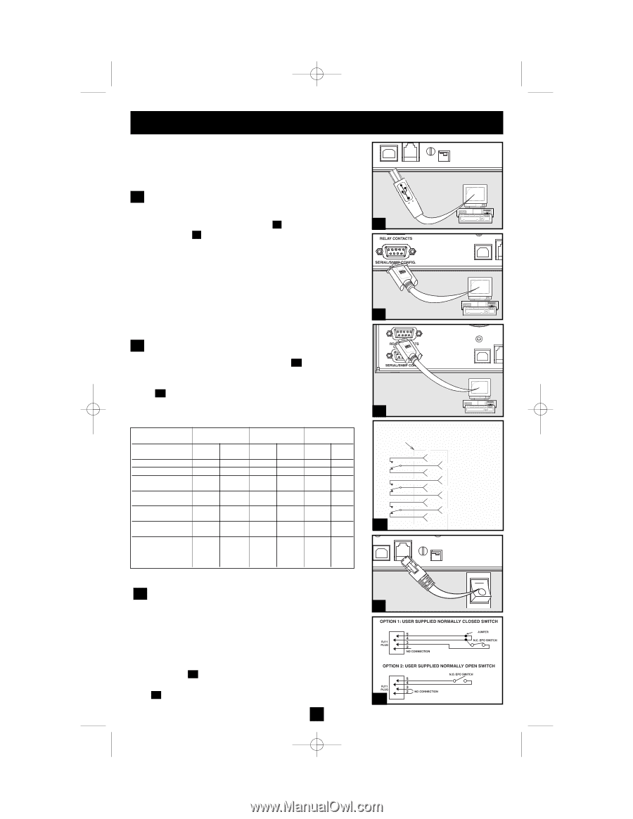
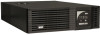
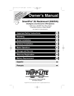
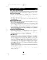
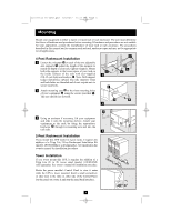
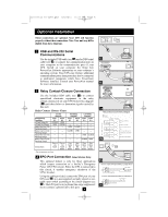
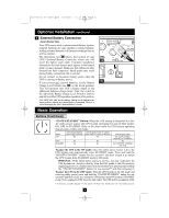
201112103 93-2459.qxd 1/9/2012 12:21 PM Page 5 Optional Installation These connections are optional. Your UPS will function properly without these connections. Note: Your unit may differ slightly from these diagrams. 1 USB and RS-232 Serial Communications Use the included USB cable (see 1a ) and/or DB9 serial 1a cable (see 1b ) to connect the communication port on your computer to the communication port of your UPS. Install on your computer the Tripp Lite PowerAlert Software appropriate to your computer's operating system. Your UPS may feature additional communications ports; these ports may also be connected to additional computers which have PowerAlert Software installed. Consult your PowerAlert manual for more information. 1b 2 Relay Contact-Closure Connection Use the included DB9 cable (see 2a ) to connect specialized electronic equipment to the relay contact-closure port on your UPS System.See diagram ( 2b ) and chart below to determine signals carried by this port. Relay Contact Closure Chart UPS Operating Conditions AC Input Voltage OK AC Input Out of Range Battery More than 3 Min. Remaining Charge* Battery Less than 3 Min. Remaining Charge* Battery More than 2 Min. Remaining Charge* Battery Less than 2 Min. Remaining Charge* Contact Action Line Fail Indication Pins 1 & 6 Pins 2 & 6 CLOSED OPEN OPEN CLOSED - - - - - - - - Open on Line Failure Close on Line Failure Battery Mid Battery Indication Pins 7 & 3 Pins 8 & 3 - - - - OPEN CLOSED Low Battery Indication Pins 4 Pins 5 & 9 & 9 - - - - - - CLOSED OPEN - - - - OPEN CLOSED - - CLOSED OPEN Close Below Mid Battery Open Below Mid Battery Close Below Low Battery Open Below Mid Battery * Times are approximate, at full load. 3 EPO Port Connection (Select Models Only) This optional feature is only for those applications which require connection to a facility's Emergency Power Off (EPO) circuit. When the UPS is connected to this circuit, it enables emergency shutdown of the UPS's inverter. Using the cable provided, connect the EPO port of your UPS (see 3a ) to a user-supplied normally closed or normally open switch according to the circuit diagram (see 3b ). The EPO port is not a phone line surge suppressor; do not connect a phone line to this port. 5 2a Relay Contact Closure Interface Diagram NO TE : TOP OF DUAL DB9 (J5/J34) J5 REMOTE CONTACTS 1 K1 A 6 LINE FAIL 2 RE LAYS SHOW N DE -ENERGIZ ED 7 K4 A 3 MID BAT 8 4 K1 0A 9 LO BATT 5 2b OPENS ON LINE FA IL COM CLOSE S ON LINE FAIL CLOSES BELOW MID BAT TERY COM OPENS BELOW MID BATTERY CLOSES BELOW LOW BATTER Y COM OPENS BELOW LOW BATTERY 3a 4-5 3b
-
 1
1 -
 2
2 -
 3
3 -
 4
4 -
 5
5 -
 6
6 -
 7
7 -
 8
8 -
 9
9 -
 10
10 -
 11
11 -
12
-
13
-
14
-
15
-
16
-
17
-
18
-
19
-
20
-
21
-
22
-
23
-
24
-
25
-
26
-
27
-
28
-
29
-
30
-
31
-
32
-
33
-
34
-
35
-
36
 |
 |