Troy-Bilt Colt FT Operation Manual - Page 14
Off-Season Storage - tiller parts
 |
View all Troy-Bilt Colt FT manuals
Add to My Manuals
Save this manual to your list of manuals |
Page 14 highlights
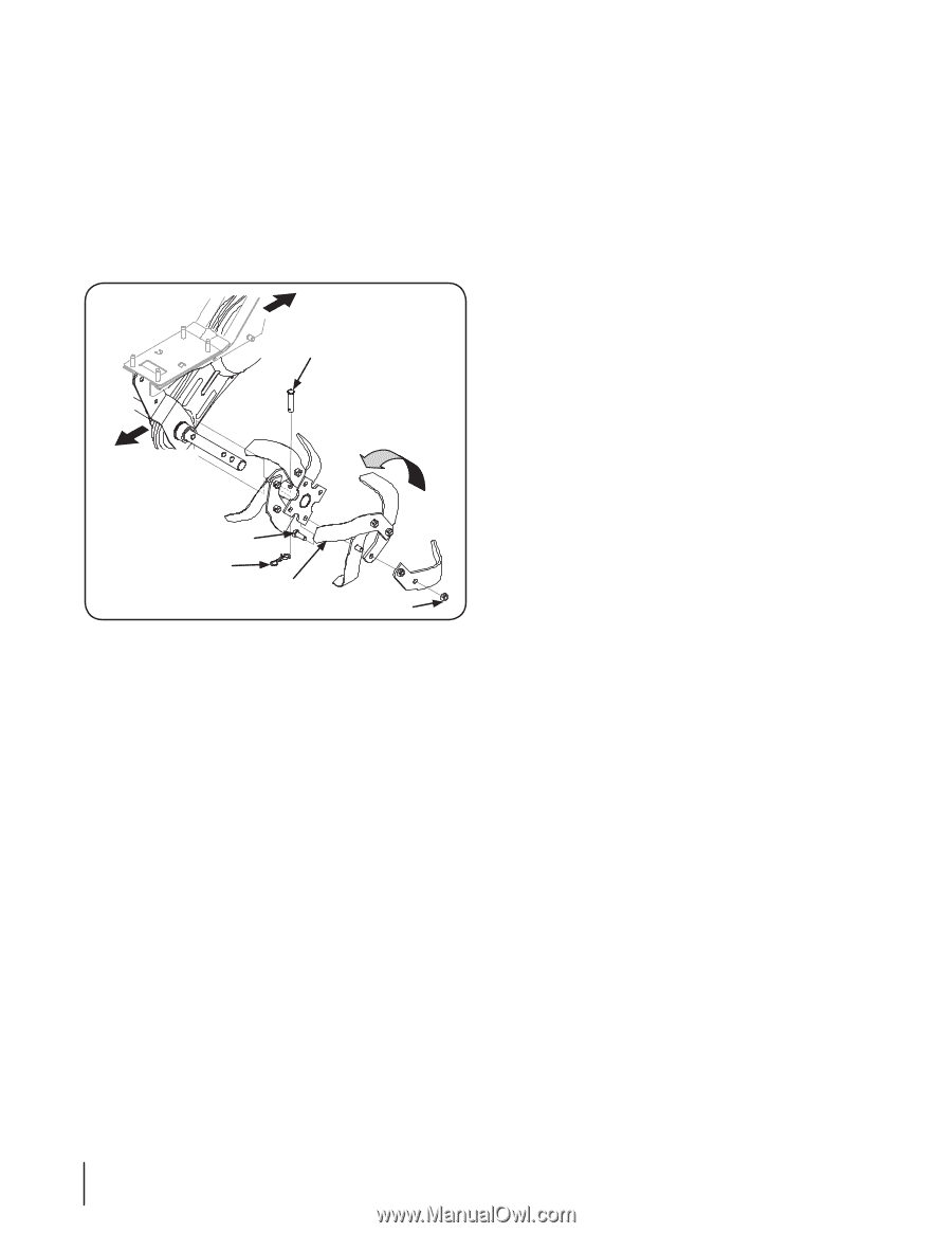
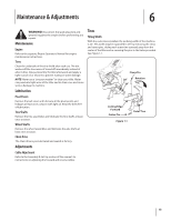
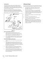
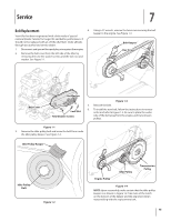
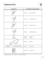
Tine Inspection The bolo tines will wear with use and should be inspected at the beginning of each tilling season and after every 30 operating hours. The tines can be replaced either individually or as a complete set. See the Replacement Parts Section for tine identification and part numbers. With use, the tines will become shorter, narrower and pointed. Badly worn tines will result in a loss of tilling depth, and reduced effectiveness when chopping up and turning under organic matter. Refer to Figure 1-2 for the following tine procedures. Rear/Operator Clevis Pin Front/Forward Rotation Off-Season Storage If the tiller will not be used for a period longer than 30 days, the following steps should be taken to prepare the tiller for storage. 1. Clean the exterior of the engine and the entire tiller thoroughly. Lubricate the tiller as described in the lubrication instructions. 2. The use of pressure washers is not recommended for cleaning your tiller. They may cause damage to electric components, spindles, pulleys, bearings or the engine. The use of pressure washers will result in shortened life and reduce serviceability. 3. Refer to the engine manual for correct engine storage instructions. 4. Wipe tines with oiled rag to prevent rust. 5. Store tiller in a clean, dry area. Do not store next to corrosive materials, such as fertilizer. NOTE: When storing any type of power equipment in an unventilated area or metal storage shed, care should be taken to rustproof the equipment. Using a light oil or silicone, coat the equipment and especially any springs, bearings, and cables. Hex Screw Cotter Pin Cutting Edge Forward Hex Lock Nut Figure 1-2 Removing/Installing a Single Tine 1. With the engine shut off and the spark plug wire disconnected, remove the two hex screws (3⁄8-16 x 1.00) and hex lock nuts (3⁄8-16) that attach a single tine to a tine holder. If needed, use penetrating oil on the nuts. 2. When installing a single tine, be sure to position it so that its cutting edge (sharp) will enter the soil first as the tiller moves forward. Removing/Installing a Tine Assembly: 1. A tine assembly consists of eight tines mounted on a tine holder. 2. If removing both tine assemblies, mark them "left" and "right" before removal. Remove the hex screw (3⁄8-16 x 1.75) and flange lock nut (3⁄8-16 ) that secure the tine assembly to the tine shaft. If necessary, use a rubber mallet to tap the tine assembly outward off the shaft. 3. Before reinstalling the tine assembly, inspect the tine shaft for rust, rough spots or burrs. Lightly file or sand, as needed. Apply a thin coat of grease to the shaft. 4. Install each tine assembly so that the cutting (sharp) edge of the tines will enter the soil first when the tiller moves forward. Secure the tine assembly to the tine shaft using the screw and locknut. 14 Section 6- Maintenance & Adjustments
-
 1
1 -
2
-
3
-
4
-
5
-
6
-
7
-
8
-
 9
9 -
 10
10 -
 11
11 -
 12
12 -
 13
13 -
 14
14 -
 15
15 -
 16
16 -
 17
17 -
 18
18 -
 19
19 -
20
-
21
-
22
-
23
-
24
-
25
-
26
-
27
-
28
-
29
-
30
-
31
-
32
-
33
-
34
-
35
-
36
 |
 |