Troy-Bilt Colt FT Operation Manual - Page 7
Assembly & Set-Up - tiller manual
 |
View all Troy-Bilt Colt FT manuals
Add to My Manuals
Save this manual to your list of manuals |
Page 7 highlights
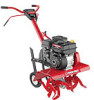
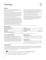
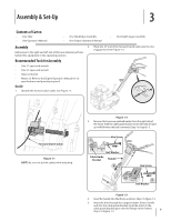
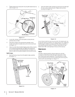
Assembly & Set-Up 3 Contents of Carton • One Tiller • One Operator's Manual • One Handlebar Assembly • One Engine Operator's Manual • One Depth Gage Assembly Assembly 2. Hook the "Z" end of the forward clutch cable into the tine engagement lever Figure 1-2. References to the right and left side of tiller are determined from behind the equipment in the operating position. Recommended Tools for Assembly • One 1⁄2" open-end wrench • One 3⁄8" open-end wrench • Clean oil funnel • Motor oil. Refer to the Engine Operator's Manual for oil specifications and quantity required. Handle 1. Identify the forward clutch cable. See Figure 1-1. Forward Clutch Cable Figure 1-1 NOTE: Be sure not to kink cables while attaching. Figure 1-2 3. Remove the hex screw and bell washer from the right side of the frame. Hold the cable guide bracket on the left side of frame as it will fall when the bolt is removed. Step 1 in Figure 1-3. Hex Screw 1 Bell Washer Cable Guide Bracket Handle 2 Hex Screw 3 Bell Washer Figure 1-3 4. Insert the handle into tiller frame as shown. Step 2 in Figure 1-3. 5. Insert the bolt through the cupped washer, frame, handle and into the cable guide bracket (note the notch in the cable guide bracket goes over the flange on the frame.) Step 3 in Figure 1-3. 7
-
 1
1 -
 2
2 -
 3
3 -
 4
4 -
 5
5 -
 6
6 -
 7
7 -
 8
8 -
 9
9 -
 10
10 -
 11
11 -
 12
12 -
13
-
14
-
15
-
16
-
17
-
18
-
19
-
20
-
21
-
22
-
23
-
24
-
25
-
26
-
27
-
28
-
29
-
30
-
31
-
32
-
33
-
34
-
35
-
36
 |
 |