Troy-Bilt Horse Tiller Technical Manual - Page 15
HORSE, MODEL, TECHNICAL, MANUAL, Transmission, Installation
 |
View all Troy-Bilt Horse Tiller manuals
Add to My Manuals
Save this manual to your list of manuals |
Page 15 highlights
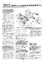
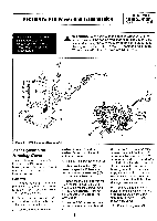
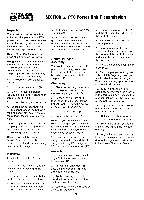
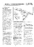
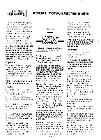
PTO HORSE MODEL SECTION 4: Transmission Removal and Installation TECHNICAL MANUAL Page 4-3 4/90 Attaching the Transmissions 1. Clean the surfaces of the transmissions where they join together. 2. Make sure the dog clutches have been greased. Fill the dog clutch cavity on the PTO power unit with grease up to where the rear of the PTO power unit widens to accept the tiller attachment. Then grease the dog clutch on the tiller attachment so that the dog clutch is covered with grease. 3. Align the locating pin on the PTO Power Unit housing with the locating hole on the tiller attachment housing and join the PTO power unit and tiller attachment. If necessary, turn the pulley on the front of the PTO power unit to adjust the dog clutch until it fits the tiller attachment dog clutch. Note: If you put the Tines/PTO Clutch in neutral you will not have to line up the dog clutches. 4. Swing the bolts so that they connect to the tiller attachment. 5. Tighten the bolts. Use a torque wrench and tighten the bolts to 70-80 ft/lbs. Transmission Installation 1. Install the wheels. 2. Install the shift lever bracket (11) with the left-side bolt and right-side bolt (the one that goes in horizontally). Be sure that the Tines/PTO Clutch Lever (13) is installed through the slot in the detent plate (15). Make sure to tighten the bolts securely. 3. Install the Wheel Speed Lever connecting rod swivel on the eccentric lever (10). 4. Install the locknut that retains the swivel to the lever. Tighten the nut securely and then loosen it 1/8 turn. 5. Install the knob (12) on the Tines/PTO Clutch Lever (13) with the bolt (9). 6. Install the handlebar mounting base and the attached handlebars to the transmission housing cover with the long bolt (8) or T-handle. 7. Install the bolt, bushing, and washer (7) that holds the yoke pivot links to each side of the PTO power unit. 8. Apply a liberal coating of grease to the engine mounting bars (5). 9. Position the engine on the PTO power unit and support the engine with a block. 10. Install one of the engine mounting bars halfway. Use a rubber hammer to tap the bar down. Take care to not damage the threads in the top of the bar. 11. Back off the jam nut and install the locking bolt (6) for the bar. Turn the bolt until it is finger tight and you feel it strike the bar. Then maintain very light pressure on the bolt with a wrench. 12. Slowly tap the engine mounting bar the rest of the way in. When the groove in the bar reaches the bolt, the pressure on the bolt will be relieved. 13. Tighten the bolt until it is snug and then back off 1/4 turn. Next, hold the bolt with one wrench while tightening the jam nut with a second wrench. 14. Repeat the previous four steps for the other engine mounting bar. 15. Install the bumper on the tiller. If the tiller did not have a bumper, install the red plugs in the top of the engine mounting bars to protect the threads in the bumper mounting holes. 16. Set the yoke in the necessary 15 position and install the bolt, bushings, and washers (4) that hold each side of the yoke to the motor mount. If necessary, temporarily detach the clutch pawl spring before attaching the yoke. Be sure to reattach the spring after the yoke is installed. 17. Attach the throttle control cable (3) to the handlebar. Use plastic wire ties to secure the cable to the handlebar. 18. On tillers so equipped, attach the Forward Interlock System plug connector with bracket (2) to the top of the shift lever bracket and install the forward bolt on the right side of the shift lever bracket. 19. On tillers so equipped, connect the Forward Interlock System engine wire harness assembly to the handlebar wire harness assembly (1). A WARNING: To help avoid personal injury, the Forward Interlock Safety System should be tested for proper functioning every time the tiller or PTO Power Unit is used. After completing all of the assembly steps, refer to "Test Operation of Forward Interlock Safety System" the PTO Horse Model Owner/Operator Manual. 20. For electric start tillers only: a. Attach the battery bracket to the transmission cover and attach the two mounting bolts and lock washers that secure the legs of the bracket. b. For Briggs & Stratton engines only: Connect the green shutoff wire on the right side of the engine.
-
 1
1 -
2
-
3
-
4
-
5
-
6
-
7
-
8
-
9
-
 10
10 -
 11
11 -
 12
12 -
 13
13 -
 14
14 -
 15
15 -
 16
16 -
 17
17 -
 18
18 -
 19
19 -
 20
20 -
21
-
22
-
23
-
24
-
25
-
26
-
27
-
28
-
29
-
30
-
31
-
32
-
33
-
34
-
35
-
36
-
37
-
38
-
39
 |
 |