Troy-Bilt Horse Tiller Technical Manual - Page 34
Special, Repairs, Procedures
 |
View all Troy-Bilt Horse Tiller manuals
Add to My Manuals
Save this manual to your list of manuals |
Page 34 highlights
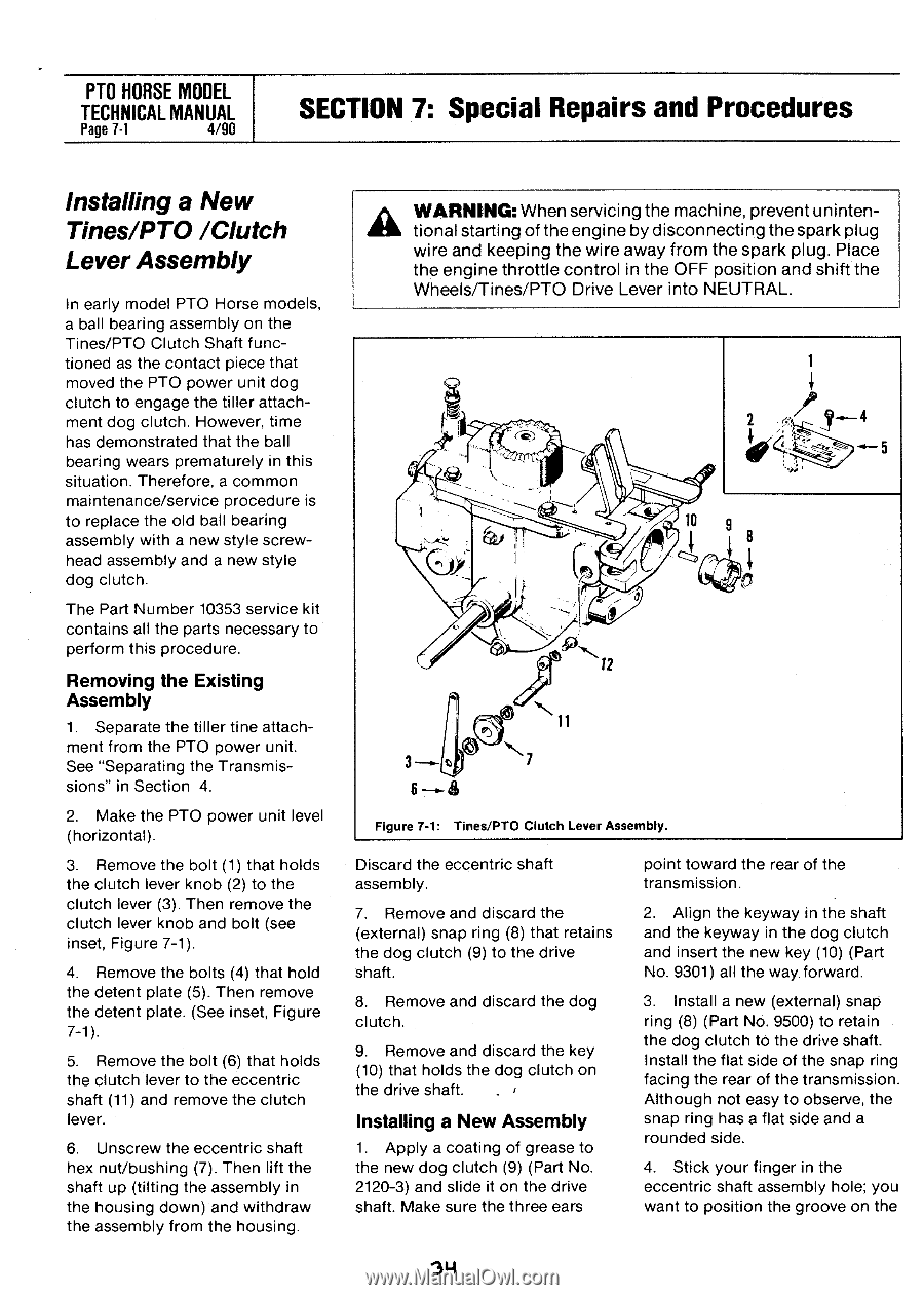
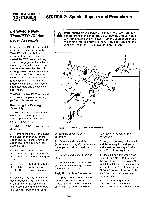
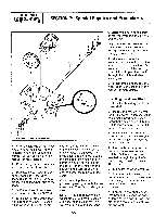
PTO HORSE MODEL TECHNICAL MANUAL Page 7.1 4/90 SECTION 7: Special Repairs and Procedures Installing a New Tines/PTO /Clutch Lever Assembly In early model PTO Horse models, a ball bearing assembly on the Tines/PTO Clutch Shaft functioned as the contact piece that moved the PTO power unit dog clutch to engage the tiller attachment dog clutch. However, time has demonstrated that the ball bearing wears prematurely in this situation. Therefore, a common maintenance/service procedure is to replace the old ball bearing assembly with a new style screwhead assembly and a new style dog clutch. The Part Number 10353 service kit contains all the parts necessary to perform this procedure. Removing the Existing Assembly 1. Separate the tiller tine attachment from the PTO power unit. See "Separating the Transmissions" in Section 4. 2. Make the PTO power unit level (horizontal). 3. Remove the bolt (1) that holds the clutch lever knob (2) to the clutch lever (3). Then remove the clutch lever knob and bolt (see inset, Figure 7-1). 4. Remove the bolts (4) that hold the detent plate (5). Then remove the detent plate. (See inset, Figure 7-1). 5. Remove the bolt (6) that holds the clutch lever to the eccentric shaft (11) and remove the clutch lever. 6. Unscrew the eccentric shaft hex nut/bushing (7). Then lift the shaft up (tilting the assembly in the housing down) and withdraw the assembly from the housing. WARNING: When servicing the machine, prevent unintentional starting of the engine by disconnecting the spark plug wire and keeping the wire away from the spark plug. Place the engine throttle control in the OFF position and shift the Wheels/Tines/PTO Drive Lever into NEUTRAL. 1 2 4 10 9 O I 3 6 & 11 N7 Figure 7-1: Tines/PTO Clutch Lever Assembly. Discard the eccentric shaft assembly. 7. Remove and discard the (external) snap ring (8) that retains the dog clutch (9) to the drive shaft. 8. Remove and discard the dog clutch. 9. Remove and discard the key (10) that holds the dog dutch on the drive shaft. Installing a New Assembly 1. Apply a coating of grease to the new dog clutch (9) (Part No. 2120-3) and slide it on the drive shaft. Make sure the three ears point toward the rear of the transmission. 2. Align the keyway in the shaft and the keyway in the dog clutch and insert the new key (10) (Part No. 9301) all the way. forward. 3. Install a new (external) snap ring (8) (Part No. 9500) to retain the dog clutch to the drive shaft. Install the flat side of the snap ring facing the rear of the transmission. Although not easy to observe, the snap ring has a flat side and a rounded side. 4. Stick your finger in the eccentric shaft assembly hole; you want to position the groove on the 34
-
 1
1 -
2
-
3
-
4
-
5
-
6
-
7
-
8
-
9
-
10
-
11
-
12
-
13
-
14
-
15
-
16
-
17
-
18
-
19
-
20
-
21
-
22
-
23
-
24
-
25
-
26
-
27
-
28
-
 29
29 -
 30
30 -
 31
31 -
 32
32 -
 33
33 -
 34
34 -
 35
35 -
 36
36 -
 37
37 -
 38
38 -
 39
39
 |
 |