Uniden MC1020 English Owners Manual - Page 6
Engine Noise Suppression, Antenna Considerations, Installing The MC 1020
 |
View all Uniden MC1020 manuals
Add to My Manuals
Save this manual to your list of manuals |
Page 6 highlights
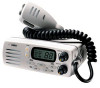
Engine Noise Suppression Interference from the impulse noise generated by the electrical systems of engines is sometimes a problem with radios. The MC 1020 has been designed to be essentially impervious to ignition impulse noise and alternator noise. However, in some installations it may be necessary to take measures to further reduce the effect of noise interference. All DC battery wires, antenna lead, and accessory cables should be routed away from the engine and engine compartment, and from power cabling carrying particularly high currents. In severe cases of impulse noise interference, it may be necessary to install a noise suppression kit. Contact your Uniden Dealer for more information. Antenna Considerations A variety of antennas is available from a number of quality suppliers. It is recommended you draw upon the advice of your Uniden Dealer in determining a suitable antenna for your vessel and range requirements. In general, communication range is increased by using a high-gain antenna placed as high as possible above the water line. Antennas should be located away from metal objects. Antennas should not have excessively long coaxial feed cables. Installing The MC 1020 After you have carefully considered the various factors affecting your choice of location, position the radio (with the bracket, microphone, power cord, antenna and any auxiliary cables installed) into the selected location to assure there is no interference with the surrounding items. Mark the location of the mounting bracket. Remove the bracket from the radio and use it as a template to mark the holes to be drilled for the mounting hardware. Drill the holes and mount the bracket with hardware compatible with the material of the mounting surface. Connect the red wire of the supplied power cord to the positive (+) battery supply. Connect the black wire of the power cord to ground. The power cord is equipped with a fuse to protect the radio. Use only a Six (6) Ampere fast blow fuse for replacement. Connect the power cord to the keyed connector on the power "pigtail" (See page 9). Connect the antenna and all other auxiliary cables and accessories. Install the radio in the mounting bracket and connect all cables and accessories to the appropriate jacks and connectors. 3
-
 1
1 -
 2
2 -
 3
3 -
 4
4 -
 5
5 -
 6
6 -
 7
7 -
 8
8 -
 9
9 -
 10
10 -
 11
11 -
 12
12 -
13
-
14
-
15
-
16
-
17
-
18
-
19
-
20
-
21
-
22
-
23
-
24
-
25
-
26
-
27
-
28
-
29
-
30
-
31
-
32
-
33
-
34
-
35
-
36
-
37
-
38
-
39
-
40
-
41
-
42
-
43
-
44
-
45
-
46
 |
 |
