Via EPIA-5000 User Manual
Via EPIA-5000 - VIA Motherboard - Mini ITX Manual
 |
View all Via EPIA-5000 manuals
Add to My Manuals
Save this manual to your list of manuals |
Via EPIA-5000 manual content summary:
- Via EPIA-5000 | User Manual - Page 1
VIA User's Manual VIA EPIA Mini-ITX Mainboard Version 1.0 March 21, 2002 P/N 99-51-010061 i - Via EPIA-5000 | User Manual - Page 2
by VIA Technologies Inc. ("VIA"). No part of this manual may be reproduced or transmitted in any form without express written authorization from VIA. Trademarks in this manual is subject to change without notice. VIA reserves the right to alter product designs, layouts or drivers without notification - Via EPIA-5000 | User Manual - Page 3
if not installed and used in accordance with the instruction manual, may cause harmful interference to radio communications. Operation power cord, if any, must be used in order to comply with the emission limits. VOIR LA NOTICE D'INSTALLATION AVANT DE RACCORDER AU RESEAU. VIA EPIA Mini-ITX Mainboard - Via EPIA-5000 | User Manual - Page 4
NOTE 1. Always read the safety instructions carefully. 2. Keep this User's Manual for future reference. 3. Keep this equipment If any of the following situations arises, get the equipment checked by a service personnel: • The power cord or plug is damaged • Liquid has penetrated into the equipment • - Via EPIA-5000 | User Manual - Page 5
Box Contents This VIA EPIA Mini-ITX Mainboard package should contain the following items: • 1 x VIA EPIA Mini-ITX Mainboard • 1 x User's manual • 1 x ATA-33/66/100 Hard drive ribbon cables • 1 x Driver Utilities CD • 1 x I/O Bracket v - Via EPIA-5000 | User Manual - Page 6
Contents 1. Specifications 1-1 Specifications 1-2 Layout 1-4 Connectors Guide 1-5 2. Installation 2-1 CPU 2-2 Memory Installation 2-4 Power Supply 2-6 Back Panel 2-7 Connectors 2-9 Jumpers 2-14 Slots 2-18 PCI Interrupt Request Routing 2-19 3. BIOS Setup 3-1 Entering Setup 3-2 Control - Via EPIA-5000 | User Manual - Page 7
4. Software Setup 4-1 VIA Apollo PLE133 Chipset Drivers 4-2 VIA PLE133 Integrated VGA Driver 4-12 VIAAudio Driver 4-14 VIA Network Driver 4-15 VIA Fast InfraRed Device Driver 4-30 vii - Via EPIA-5000 | User Manual - Page 8
ultra-compact and highly intergrated VIA EPIA Mini-ITX Mainboard is the smallest form factor mainboard specification available today, developed by VIA Technologies, Inc as part of the company's open industry-wide Total Connectivity initiative. The VIA EPIA Mini-ITX mainboard enables the creation of - Via EPIA-5000 | User Manual - Page 9
, Line-out and Mic-in Main Memory • 2 x PC100/133 DIMM slots. PCI Bus IDE • Supports up to 4 IDE devices • Ultra DMA 33/66/100 LAN • VIA VT6103 Ethernet PHY • Supports Ethernet 10/100Mb USB • 2 USB ports • 1 onboard USB pin header for up to 2 additional connections • USB v1.1 and Intel Universal HCI - Via EPIA-5000 | User Manual - Page 10
Specifications TV-Out • VIA VT1621 TV-Out Controller • Supports 640 x 480, 800 x 600 NTSC/PAL TV • S-Video or RCA Video output I/O Ports • 1 PS2 Mouse connenctor • 1 PS2 Keyboard connector • 1 15-pin External Monitor connector • 1 16C550 compliant serial port • 1 EPP/ECP complaint parallel port • 1 - Via EPIA-5000 | User Manual - Page 11
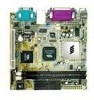
Chapter 1 Layout VIA EPIA Mini-ITX Mainboard (Note: Onboard DOC is optional) 1-4 - Via EPIA-5000 | User Manual - Page 12
Connectors Guide Specifications Component Fan 1, Fan 2 DIMM1, DIMM2 ATX Power Connector PS/2 Mouse PS/2 Keyboard LPT Connector RJ-45 Port COM Port Line Out Line In Mic In USB 0, USB 1 RCA Video or S/P DIF S-Video CRT connector IDE 1, IDE 2 J3 J7 J5 J6 J8 J9 J12 J10 J13 J2 J1 J4 J11 PCI Slot - Via EPIA-5000 | User Manual - Page 13
components. The components can be damaged by static electricity. This chapter contains the following topics: Central Processing Unit (CPU) 2-2 Memory Installation 2-4 Power Supply 2-6 Back Panel 2-7 Connectors 2-9 Jumpers 2-14 Slots 2-18 PCI Interrupt Request Routing 2-19 2-1 - Via EPIA-5000 | User Manual - Page 14
EPIA Mini-ITX Mainboard includes an embedded VIA Eden Processor or VIA C3TM E-Series Processor. Two fan connectors (Fan 1 & Fan 2) are provided on the mainboard, alllowing for the connection of a CPU fan and an additional system case fan. The VIA C3TM E-Series Processor With low power consumption - Via EPIA-5000 | User Manual - Page 15
VIA Eden Processor Providing ultra-low power consumption and advanced thermal dissipation properties, the VIA Eden Processor features a fanless design. The VIA Eden Processor requires only a heatsink, as shown below. CPU Heatsink Overclocking This motherboard is not designed to support overclocking - Via EPIA-5000 | User Manual - Page 16
Chapter 2 Memory Installation The VIA EPIA Mini-ITX Mainboard provides two 168-pin DIMM slots for PC 100/133 SDRAM memory modules. To operate properly, at least one module must be installed. DIMM 1 & DIMM 2 SDRAM Module Installation Procedures 1.) Push the white retaining latches at either end - Via EPIA-5000 | User Manual - Page 17
SDRAM Configurations Refer to the table below for available SDRAM configurations on the VIA EPIA Mini-ITX Mainboard. Socket Memory Module Total Mem ory DIMM 1 DIMM 2 32MB, 64MB, 128MB, 32MB~512MB 256MB, 512MB 32MB, 64MB, 128MB, 32MB~512MB 256MB, 512MB Maximum System Memory Supported 1GB 2-5 - Via EPIA-5000 | User Manual - Page 18
2 Power Supply The VIA EPIA Mini-ITX Mainboard requires an ATX power supply to be connected. Before inserting the power supply connector, always make sure that all components are installed correctly to ensure that no damage will be caused. ATX 20-Pin Power Connector To connect the ATX power supply - Via EPIA-5000 | User Manual - Page 19
Hardware Setup Back Panel The back panel of the VIA EPIA Mini-ITX Mainboard contains the following connectors: PS/2 Mouse LPT Connector RJ-45 Port COM Port PS/2 Keyboard S-Video Port USB Ports Line Line Mic CRT Connector RCA Video or Out In In (Audio Connectors) S / P DIF Port PS/2 - Via EPIA-5000 | User Manual - Page 20
connection. S-Video Port This port supporting 640 x 480 and 800 x 600 resolutions in NTSC and PAL modes. If RCA Video function is selected, and both RCA Video/SVideo port are connected, only S-Video function will be enabled. CRT Connector Connect a CRT monitor to this connector for VGA display. 2-8 - Via EPIA-5000 | User Manual - Page 21
Hardware Setup Connectors The VIA EPIA Mini-ITX Mainboard provides the following connectors: IDE Connectors The two PCI IDE connectors (IDE 1 & IDE 2) support Ultra DMA 33/66/ 100 modes. IDE 1 is refer to the HDD documentation supplied by the HDD vendor for correct jumper setiing instructions. 2-9 - Via EPIA-5000 | User Manual - Page 22
Chapter 2 Front Panel Connectors (J3) The J3 front panel connectors allow you to connect the Power Switch, Reset Switch, Power LED and HDD LED to the system case. 1 HDD LED Power Switch Reset 11 2 Power LED 12 CD-ROM Line In Connector (J7) The J7 internal CD-ROM Line In Connector allows you to - Via EPIA-5000 | User Manual - Page 23
(J5) allows you to connect a Fast Infrared standard module. This is not for standard FIR module, for reference design please consult with VIA Technologies, Inc. 1 CIR Module Connector (J6) The CIR Module Connector (J6) allows you to connect a Consumer Infrared standard module. This is not for - Via EPIA-5000 | User Manual - Page 24
Serial Bus (USB) ports, in case the two USB ports on the back panel are not sufficient. To utilize the additional two USB connections you need to connect a 2 port USB module to the J9 connector. This is not for standard USB port module, for reference design please consult with VIA Technologies, Inc - Via EPIA-5000 | User Manual - Page 25
PCI Riser Card Connector (left part of J12, see diagram below) allows you to connect a PCI Riser Card module. These connectors are not for standard Video In and PCI Riser Card module, for reference design please consult with VIA Technologies, Inc. 1 Video In Connector PCI Riser Card Connector 2-13 - Via EPIA-5000 | User Manual - Page 26
The VIA EPIA Mini-ITX Mainboard provides a series of jumpers to set the computer's functions. This section explains the functions of all the mainboard settings. Clear CMOS (J10) The Clear CMOS jumper allows you to clear the CMOS memory of system parameter settings. If you want to clear the system - Via EPIA-5000 | User Manual - Page 27
select the host frequency bus speed of the mainboard. The three available options are 66MHz, 100MHz and 133MHz. J13 Host Frequency Select WARNING!Overclocking This motherboard is not designed to support overclocking. Any attempt to operate beyond product specifications is not recommended. We do not - Via EPIA-5000 | User Manual - Page 28
enables or disables the Auto Reboot Function Setting. When enabled, the system will automatically reboot in the event of sudden power outage. 1 1-2: Disable 2-3: Enable CPU Strapping Function Setting (J1) This jumper enables or disables the CPU Strapping Function Setting. 1 1-2: Disable 2-3: Enable - Via EPIA-5000 | User Manual - Page 29
disables the Disk on Chip (DOC) BIOS Select Function. The DOC function is not a standard option on this mainboard and is a manufacturing option only. Therefore the DOC function may not be present on the mainboard you have purchased. 1 1-2: Disable 2-3: Enable RCA Video or S/P DIF Select (J11) This - Via EPIA-5000 | User Manual - Page 30
adding or removing expansion cards, make sure that you unplug the power supply first. Meanwhile, read the documentation for the expansion card to make or BIOS configuration. For two PCI slot solution, a PCI Riser Card module can be used. For reference design please consult with VIA Technologies, - Via EPIA-5000 | User Manual - Page 31
Hardware Setup PCI Interrupt Request Routing The IRQ (Interrupt ReQuest) is the mechanism for devices to request services from the microprocessor. The "PCI & LAN" IRQ pins are typically connected to the PCI bus INT A# ~ INT D# pins as follows: PCI Slot 1 LAN Order 1 INT B# - Via EPIA-5000 | User Manual - Page 32
CMOS Features 3-6 Advanced BIOS Features 3-8 Advanced Chipset Features 3-11 Integrated Peripherals 3-15 Power Management Setup 3-20 PNP/PCI Configurations 3-26 PC Health Status 3-29 Load Fail-Safe Defaults 3-30 Load Optimized Defaults 3-31 Set Supervisor/User Password 3-32 Save - Via EPIA-5000 | User Manual - Page 33
Chapter 3 Entering Setup Power on the computer and press DEL straight away to enter the BIOS setup menu. If you missed the BIOS setup entry point, you may restart the system and try again. Control Keys E nte r> < + /P U > < -/P D > M o v e to th e p re vio u s ite - Via EPIA-5000 | User Manual - Page 34
Main Menu appears. Main Menu The main menu displays all BIOS setup categories. Use the control keys (LK) to Primary Master IDE Primary Slave IDE Secondary Master IDE Secondary Slave General Help The BIOS setup program provides a General Help screen. You can call up this screen from any menu - Via EPIA-5000 | User Manual - Page 35
CMOS Features Use this menu to set basic system configurations. Advanced BIOS Features Use this menu to set the advanced features available on your system. Advanced Chipset Features Use this menu to set chipset specific features and optimize system performance. Integrated Peripherals Use this menu - Via EPIA-5000 | User Manual - Page 36
Optimized Defaults Use this menu to load BIOS default settings for optimal and high performance system operations. Set Supervisor Password Use this menu to set supervisor password. Set User Password Use this menu to set user password. Save & Exit Setup Save BIOS setting changes and exit setup. Exit - Via EPIA-5000 | User Manual - Page 37
the date from 1 to 31. Year - the year, range from 1994 to 2079. Time The time format is . Video Set the video mode. Available options are EGA/VGA, CGA 40, CGA 80 and Mono. Halt On Determine the system behaviour if an error is detected during bootup. Settings: All Errors - Via EPIA-5000 | User Manual - Page 38
sub-menu and the following screen appears: The specifications of your drive must match with the drive table. The hard disk will not work properly if you enter improper information for this category. Select Auto whenever possible. If you select Manual, make sure the information provided is from your - Via EPIA-5000 | User Manual - Page 39
: Enabled and Disabled. Quick Power On Self Test Shorten Power On Self Test (POST) cycle and enable shorter bootup time. Allow BIOS to skip some check items during POST. Settings: Enabled and Disabled. First/Second/Third Boot Device Set the boot device sequence as BIOS attempts to load the disk - Via EPIA-5000 | User Manual - Page 40
BIOS Setup LS120 HDD-0 SCSI CD-ROM HDD-1 HDD-2 HDD-3 ZIP100 USB-FDD USB-ZIP USB-CDROM USB-HDD LAN Disabled The system will boot from LS-120 drive. The system will boot from first HDD. The system will boot from SCSI. The system will boot from CD-ROM. The system will boot from second HDD. The system - Via EPIA-5000 | User Manual - Page 41
to run Setup. System A password prompt appears every time when the computer is powered on or when end users try to run Setup. OS Select For DRAM > 64MB Select the OS type used. Settings: Non-OS2 and OS2. Video BIOS Shadow Enable shadow for the Video BIOS. Settings: Disabled and Enabled. C8000 - Via EPIA-5000 | User Manual - Page 42
only if you are familiar with the chipset. Memory Hole Select whether to have a memory hole at 15M to 16M area. Settings: Disabled and 15M-16M. System BIOS Cacheable Cache the System Bios. Settings: Disabled and Enabled. Video RAM Cacheable Cache the Video RAM. Settings: Disabled and Enabled. TV - Via EPIA-5000 | User Manual - Page 43
Chapter 3 DRAM Clock/Drive Control Press to enter the sub-menu and the following screen appears: DRAM Clock Set the DRAM Clock. Settings: Host CLK, HCLK-33M and By Auto. DRAM Timing By SPD Set DRAM Timing by SPD. Settings: Disabled and Enabled. SDRAM Cycle Length Set the SDRAM Cycle Length. - Via EPIA-5000 | User Manual - Page 44
BIOS Setup AGP & P2P Bridge Control Press to enter the sub-menu and the following screen appears: AGP Aperture Size Set the AGP Aperture Size. - Via EPIA-5000 | User Manual - Page 45
Chapter 3 CPU & PCI Bus Control Press to enter the sub-menu and the following screen appears: P2C/C2P Concurrency Set the P2C/C2P Concurrency. Settings: Disabled and Enabled. Fast R-W Turn Around Set the Fast R-W Turn Around. Settings: Disabled and Enabled. CPU to PCI Write Buffer Set the - Via EPIA-5000 | User Manual - Page 46
the frame buffer size. Settings: 2M, 4M and 8M. OnChip USB Set the state of the OnChip USB. Settings: Enabled and Disabled. USB Keyboard Support This setting specifies whether it is neccessay for BIOS to provide support for USB Keyboard. Settings: Disabled and Enabled. IDE HDD Block Mode This - Via EPIA-5000 | User Manual - Page 47
Chapter 3 VIA OnChip IDE Device Press to enter the sub-menu and the following screen appears: OnChip IDE Channel 0/1 The integrated peripheral controller contains an IDE interface with support for two IDE channels. Choose Enabled to activate each channel separately. Settings: Disabled and - Via EPIA-5000 | User Manual - Page 48
BIOS Setup Primary Master/Slave UDMA These settings specifies the UDMA mode for Primary Master/Slave IDE devices. Settings: Disabled and Auto. Secondary Master/Slave UDMA These settings specifies the UDMA mode for Secondary Master/ Slave IDE devices. Settings: Disabled and Auto. VIA OnChip PCI - Via EPIA-5000 | User Manual - Page 49
. Settings: 300-303H, 310-313H, 320323H and 330-333H. Game Port (200-207H) Set the game port at address (200-207H). Settings: Disabled and Enabled. VIA SuperIO Device Press to enter the sub-menu and the following screen appears: 3-18 - Via EPIA-5000 | User Manual - Page 50
port address and IRQ for the onboard serial port 1. Selecting Auto allows BIOS to automatically determine the correct base I/O port address. Settings: Disabled, Choosing "ECP + EPP" will allow the onboard parallel port to support both the ECP and EPP modes simultaneously. Settings are: Normal : - Via EPIA-5000 | User Manual - Page 51
. In this state, no system context (CPU or chipset) is lost and hardware maintains all system context. S3/STR - S3/Suspend To RAM (STR) is a power-down state. In this state, power is supplied only to essential components such as main memory and wakeup-capable devices. The system context is saved - Via EPIA-5000 | User Manual - Page 52
BIOS Setup Video Off Option Select whether or not to turn off the screen when system enters power saving mode, ACPI OS such as Windows XP will override this option. Settings are: Always On - The screen is always on even when system enters power saving mode. Suspend -> Off - The screen is turned off - Via EPIA-5000 | User Manual - Page 53
to preset options or user define parameters. Min Saving - minimal power saving, provide the optimal performance. Max Saving - minimal power consumption. Settings: User Define, Min Saving and Max Saving. HDD Power Down The HDD power down timer. Settings: Disable, 1 ~ 15Min. Doze Mode Set the doze - Via EPIA-5000 | User Manual - Page 54
BIOS Setup Wake Up Events Press to enter the sub-menu and Disabled and Enabled. USB Resume from S3 Decide whether or not the USB devices can wake the system from S3. Settings: Disabled and Enabled. VGA Decide whether or not the power management unit should monitor VGA activities. Settings: - Via EPIA-5000 | User Manual - Page 55
master activties. Settings: Off and On. PowerOn by PCI Card Decide whether or not a PCI card can power up the system or resume it from suspend state. Such PCI cards include LAN, onboard USB ports, etc. Settings: Disabled and Enabled. Modem Ring Resume Decide whether or not Ring-In signals from Modem - Via EPIA-5000 | User Manual - Page 56
BIOS Setup IRQs Activities Monitoring Press to enter the sub-menu and the following screen appears: Primary INTR Selecting ON will cause the system to wake up from power saving modes if activity ready, the system will interrupt itself and perform the service required by the IO device. 3-25 - Via EPIA-5000 | User Manual - Page 57
Installed When set to Yes, BIOS will only initialize the PnP cards used for booting (VGA, IDE, SCSI). Other cards boot. The settings: Enabled and Disabled. PCI/VGA Palette Snoop Set the PCI/VGA Palette Snoop option. Settings: Disabled and Enabled. Assign IRQ For VGA/USB Assign IRQ for VGA and USB - Via EPIA-5000 | User Manual - Page 58
Setup Resource Controlled By The BIOS can automatically configure all the boot and Plug and Play compatible devices. Choose "Auto(ESCD)" if unsure, the BIOS will automatically assign IRQ, DMA and memory base address fields. The settings: Auto (ESCD) and Manual. IRQ Resources The items are adjustable - Via EPIA-5000 | User Manual - Page 59
Chapter 3 DMA Resources The items are adjustable only when Resources Controlled By is set to Manual. Press and you will enter the sub-menu of the items. Resources list DMA 0/1/3/5/6/7 for users to set each DMA channel type. Settings: PCI/ - Via EPIA-5000 | User Manual - Page 60
BIOS Setup PC Health Status This section shows the status of your CPU, fan, warning for overall system status. CPU Fan Speed, CPU Fan 2 Speed, 12V, 5V, 2.5V, Vcore and Internal VCC. These items display the current status of all of the monitored hardware devices/components such as fan speed. 3-29 - Via EPIA-5000 | User Manual - Page 61
Chapter 3 Load Fail-Safe Defaults This option on the main menu allows users to restore all the BIOS settings to the default Fail Safe values. These values are set by the mainboard manufacturer to provide the most stable system. When you select Load-Fail Safe Defaults, a message as below appears: - Via EPIA-5000 | User Manual - Page 62
on the main menu allows users to restore all the BIOS settings to the default Optimized values. The Optimized Defaults are the default values also set by the mainboard manufacturer for both optimized and stable performance of the mainboard. When you select Load Optimized Defaults, a message as below - Via EPIA-5000 | User Manual - Page 63
Supervisor/User Password When you select this function, a message as below will appear on the screen: Type the password, up to eight characters in length, and press . The password typed now will clear any previously set password from CMOS memory. You will be prompted to confirm the password - Via EPIA-5000 | User Manual - Page 64
BIOS Setup Setup. If set to Setup, password prompt only occurs when trying to enter Setup. About Supervisor Password & User Password: Supervisor password : Can enter and change the settings of the setup menus. User password: Can only enter but do not have the right to change the settings of - Via EPIA-5000 | User Manual - Page 65
Chapter 3 Save & Exit Setup When you want to quit the Setup menu, you can select this option to save the changes and quit. A message as below will appear on the screen: Typing "Y" will allow you to quit the Setup Utility and save the user setup changes to RTC CMOS. Typing "N" will return to the - Via EPIA-5000 | User Manual - Page 66
BIOS Setup Exit Without Saving When you want to quit the Setup menu, you can select this option to abandon the changes. A message as below will - Via EPIA-5000 | User Manual - Page 67
instructions on setup of motherboard drivers and applications. It consists of the following topics: VIAApollo PLE133 Chipset Drivers 4-2 VIA PLE133 Integrated VGA Driver 4-12 VIA Audio Driver 4-14 VIA Network Driver 4-15 VIA Fast InfraRed Driver 4-30 Note: You must install VIA 4in1 chipset - Via EPIA-5000 | User Manual - Page 68
VGA Support, minimum 640 x 480 reso- lution Operating system Windows® 95/98/98SE, Windows® NT3.51 or 4.0, Windows® ME, Win- dows® 2000, or Windows® XP CD-ROM Double speed or higher Chipset VIA Apollo PLE133 chipset 4in1 chipset driver installation for Windows XP 1. Insert the supplied - Via EPIA-5000 | User Manual - Page 69
installation starts, click Next to view the VIA Service Pack README. 5. Click Yes to proceed. 6. The screen now will show two installation options. Select Normally Install to manually install every driver, else select Quickly Install to install the drivers automatically. Click Next to continue, for - Via EPIA-5000 | User Manual - Page 70
Chapter 4 8. The screen now should show one driver: Install VIA PCI IDE Bus Driver. Please select the driver and click on Next to continue. 9. After all chipset drivers are properly installed please select "Yes, I want to restart my computer now." and click Finish to restart your computer and - Via EPIA-5000 | User Manual - Page 71
2000 1. Insert the supplied CD into the CD-ROM drive. 2. The CD should run automatically and the setup screen will appear. If not, please run the "setup.exe" within the CD manually. 3. On the setup screen click on the Install VIA Chipset Drivers option to install the VIA Service Pack 4. 4. When the - Via EPIA-5000 | User Manual - Page 72
Chapter 4 8. Select Install VIA PCI IDE Bus Driver and click Next to continue. 9. Select Install AGP 4X/133 driver and click Next to continue. 10. After all chipset drivers are properly installed please select "Yes, I want to restart my computer now." and click Finish to restart your computer and - Via EPIA-5000 | User Manual - Page 73
/98SE 1. Insert the supplied CD into the CD-ROM drive. 2. The CD should run automatically and the setup screen will appear. If not, please run the "setup.exe" within the CD manually. 3. On the setup screen click on the Install VIA Chipset Drivers option to install the VIA Service Pack 4. 4. When the - Via EPIA-5000 | User Manual - Page 74
to manually install every driver, else select Quickly Install to install the drivers automatically. Click Next to continue, for Quickly Install users please go to step 12. 7. The screen will now show four drivers: VIA ATAPI Vendor Support Driver. AGP VxD Driver. IRQ Routing Miniport Driver. VIA INF - Via EPIA-5000 | User Manual - Page 75
Support Driver and click Next to continue. 9. Select Click to enable DMA Mode option and click Next to continue. 10. Select Install VIA AGP VxD in Turbo mode and click Next to continue. 11. Select Install VIA IRQ Routing Miniport Driver and click Next to continue. 12. After all chipset drivers - Via EPIA-5000 | User Manual - Page 76
ME 1. Insert the supplied CD into the CD-ROM drive. 2. The CD should run automatically and the setup screen will appear. If not, please run the "setup.exe" within the CD manually. 3. On the setup screen click on the Install VIA Chipset Drivers option to install the VIA Service Pack 4. 4. When the - Via EPIA-5000 | User Manual - Page 77
Software Setup 9. Select Click to enable DMA Mode option and click Next to continue. 10. Select Install VIA AGP VxD in Turbo mode and click Next to continue. 11. After all chipset drivers are properly installed please select "Yes, I want to restart my computer now." and click Finish to restart your - Via EPIA-5000 | User Manual - Page 78
Chapter 4 VIA PLE133 Integrated VGA Driver VGA driver installation for Windows 98/98SE/ME/2000/XP 1. Insert the supplied CD into the CD-ROM drive. 2. The CD should run automatically and the setup screen will appear. If not, please run the "setup.exe" within the CD manually. 3. On the setup screen - Via EPIA-5000 | User Manual - Page 79
Software Setup 5. After the VGA driver is properly installed, please select "Yes, I want to restart my computer now." And click Finish to restart your computer and complete the installation. 4-13 - Via EPIA-5000 | User Manual - Page 80
98/98SE/ME/2000/XP 1. Insert the supplied CD disc into the CD-ROM drive. 2. The CD should run automatically and the setup screen will appear. If not, please run the "setup.exe" within the CD manually. 3. On the setup screen click the Install VIA Audio Driver. 4. Select Install driver. Click Next to - Via EPIA-5000 | User Manual - Page 81
Software Setup VIA Network Driver Network driver installation for Windows XP 1. Put the supplied CD into the CD ROM drive and double click "System" in the "Control Panel". 2. The "System Properties" window is popped. Select the "Hardware" tab. And click the "Device Manager" button. 4-15 - Via EPIA-5000 | User Manual - Page 82
Chapter 4 3. The "Device Manager" window is popped. Then, select the "VIA PCI 10/100Mb Fast Ethernet Adapter" and click right button to select the "Properties". 4. In the "VIA PCI 10/100Mb Fast Ethernet Adapter Properties" window, select "Update Driver" button. 4-16 - Via EPIA-5000 | User Manual - Page 83
Software Setup 5. Once the "Update Device Driver Wizard" is invoked. Select "Next" to continue. 6. Select "Don't search, I will choose the driver to install" and click "Next" button to continue. 4-17 - Via EPIA-5000 | User Manual - Page 84
Chapter 4 7. Select "VIA PCI 10/100Mb Fast Ethernet Adapter" for driver and click "Have Disk..." to find driver location. 8. Click "Browse" button to find driver location. In this case, the driver is in "E:\DRIVERS\LAN". Then click "OK" to continue. 4-18 - Via EPIA-5000 | User Manual - Page 85
Software Setup 9. Find the suitable device "VIA 10/100Mb Fast Ethernet Adapter" from the location E:\Drivers\LAN, and click "Next" button to continue. 10. Complete upgrading the driver and click "Finish" to close wizard. 4-19 - Via EPIA-5000 | User Manual - Page 86
Chapter 4 Network driver installation for Windows 2000 1. Put the supplied CD in the CD ROM drive and click the "Start", "Setting" and "Control Panel" sequentially. And double click "System". 2. The "System Properties" window is popped. - Via EPIA-5000 | User Manual - Page 87
" window is popped. Then, select the "Ethernet controller" and click right mouse button, and select the "Properties". 4. In the "Ethernet Controller Properties" window. Select "Reinstall Driver" button. 5. The "Update Device Driver Wizard" is invoked. Select "Next" to continue. 4-21 - Via EPIA-5000 | User Manual - Page 88
Chapter 4 6. Select "Search for a suitable driver for my device [recommended]" and click "Next" to continue. 7. Select "Specify a location" for driver and click "Next" to continue. 4-22 - Via EPIA-5000 | User Manual - Page 89
8. Click "Browse" button to find driver location. In this case, the driver is in "E:\DRIVERS\LAN". Then click "OK" to continue. 9. Find the suitable driver from the location "E:\Drivers\LAN", and click "Next" to continue. 10. Completing the Upgrade Device Driver and click "Finish" to close wizard - Via EPIA-5000 | User Manual - Page 90
Chapter 4 Network driver installation for Windows 98/98SE 1. Put the supplied CD in the CD ROM drive and right click the "My Computer" icon on the desktop. Move mouse pointer to "Properties" item and left click - Via EPIA-5000 | User Manual - Page 91
Software Setup 3. In the "PCI Ethernet Controller Properties" window, click the "Reinstall Driver" button. 4. The "Update Device Driver Wizard" is invoked, then click "Next" to continue. 5. Select "Search for a better driver than the one your device is using now. [Recommended]" item and click "Next" - Via EPIA-5000 | User Manual - Page 92
Chapter 4 6. Click "Browse" to find driver location. In this case, the driver is in "E:\DRIVERS\LAN". Then click "Next" to continue. 7. Completing the Upgrade Device Driver and click "Finish" to close wizard. 4-26 - Via EPIA-5000 | User Manual - Page 93
Software Setup Network driver installation for Windows ME 1. Put the supplied CD in the CD ROM drive and right click the "My Computer" icon on the desktop. Move mouse pointer to "Properties" item and left click - Via EPIA-5000 | User Manual - Page 94
Chapter 4 3. In the "VIA PCI 10/100Mb Fast Ethernet Adapter Properties" window, select the "Driver" tab and click the "Update Driver" button. 4. The "Update Device Driver Wizard" is invoked. Select "Specify the location of the driver [Advanced]" and click "Next" to continue. 4-28 - Via EPIA-5000 | User Manual - Page 95
is using now. [Recommended]" and use "Browse" button to specify a location: E:\DRIVERS\LAN". Then click "Next" to continue. 6. Select "The updated driver [Recommended] VIA PCI 10/100Mb Fast Ethernet Adapter" to update new driver. Then click "Next" to continue. 7. Click "Next" of the "Update Device - Via EPIA-5000 | User Manual - Page 96
Fast InfraRed Device Driver VIA Fast InfraRed Device Driver installation for Windows XP 1. Put the supplied CD into the CD ROM drive and double click "System" in the "Control Panel". 2. The "System Properties" window is popped. Select the "Hardware" tab. And - Via EPIA-5000 | User Manual - Page 97
Software Setup 3. The "Device Manager" window is popped. Then, select the "VIA Fast InfraRed Controller" and click right button to select the "Properties". 4. In the "VIA Fast InfraRed Controller Properties" window, select "Update Driver" button. 4-31 - Via EPIA-5000 | User Manual - Page 98
Chapter 4 5. Once the "Update Device Driver Wizard" is invoked. Select "Next" to continue. 6. Select "Don't search, I will choose the driver to install" and click "Next" button to continue. 4-32 - Via EPIA-5000 | User Manual - Page 99
Software Setup 7. Select "VIA Fast InfraRed Controller" for driver and click "Have Disk..." to find driver location. 8. Click "Browse" button to find driver location. In this case, the driver is in "E:\DRIVERS\FIR\WINXP". Then click "OK" to continue. 4-33 - Via EPIA-5000 | User Manual - Page 100
Chapter 4 9. Find the suitable device "VIA Fast InfraRed Controller" from the location, and click "Next" button to continue. 10. Complete upgrading the driver and click "Finish" to close wizard. 4-34 - Via EPIA-5000 | User Manual - Page 101
Software Setup VIA Fast InfraRed Device Driver installation for Windows 2000 1. Put the supplied CD into the CD ROM drive and double click "System" in the "Control Panel". 2. The "System Properties" window is popped. Select the "Hardware" tab. And click the "Device Manager" button. 4-35 - Via EPIA-5000 | User Manual - Page 102
Chapter 4 3. The "Device Manager" window is popped. Then, select the "Unknown device" and click right button to select the "Properties". 4. In the "Unknown device Properties" window, select "Reinstall Driver" button. 5. The "Update Device Driver Wizard" is invoked. Click "Next" to continue. 4-36 - Via EPIA-5000 | User Manual - Page 103
Software Setup 6. Select "Search for suitable driver for my device [recommended]" and click "Next" to continue. 7. Select "Specify a location" for driver. Then click "Next" to continue. 4-37 - Via EPIA-5000 | User Manual - Page 104
Chapter 4 8. Click "Browse" to find driver location. In this case, the driver is in supplied CD under "E:\DRIVERS\FIR\WIN2000". Click "OK" to continue. 9. Find the suitable driver from the location and click "Next" to continue. 10. Completing the "Upgrade Device Driver Wizard" and click "Finish" to - Via EPIA-5000 | User Manual - Page 105
Software Setup VIA Fast InfraRed Device Driver installation for Windows 98/98SE 1. Put the supplied CD into the CD ROM drive and double click "System" in the "Control Panel". 2. button. 3. In the "Unknown Device Properties" window. Select "General" tab and click the "Reinstall Driver" button. 4-39 - Via EPIA-5000 | User Manual - Page 106
than the one your device is using now. [Recommended]" and click "Next" to continue. 6. Specify the location of the driver by clicking on "Browse" button. The location should be "E:\DRIVERS\FIR\WIN98SE". Then click the "Next" button. 7. Click "Next" in the "Add New Hardware Wizard" dialog. 8. Click - Via EPIA-5000 | User Manual - Page 107
Software Setup VIA Fast InfraRed Device Driver installation for Windows ME 1. Put the supplied CD into the CD ROM drive and double click "System" in the "Control Panel". 2. The "System Properties" window is popped. Select the "Device Manager" tab ( - Via EPIA-5000 | User Manual - Page 108
4 5. Select "Search for a better driver than the one your device is using now. [Recommended]" and click "Browse" to set the location to CD-ROM drive under directory "E:\DRIVERS\FIR\WINME". Click "Next" to continue. 6. Click "Next" in the "Update Device Driver Wizard" dialog. 8. Click "Finish" to
-
 1
1 -
 2
2 -
 3
3 -
 4
4 -
 5
5 -
 6
6 -
 7
7 -
8
-
9
-
10
-
11
-
12
-
13
-
14
-
15
-
16
-
17
-
18
-
19
-
20
-
21
-
22
-
23
-
24
-
25
-
26
-
27
-
28
-
29
-
30
-
31
-
32
-
33
-
34
-
35
-
36
-
37
-
38
-
39
-
40
-
41
-
42
-
43
-
44
-
45
-
46
-
47
-
48
-
49
-
50
-
51
-
52
-
53
-
54
-
55
-
56
-
57
-
58
-
59
-
60
-
61
-
62
-
63
-
64
-
65
-
66
-
67
-
68
-
69
-
70
-
71
-
72
-
73
-
74
-
75
-
76
-
77
-
78
-
79
-
80
-
81
-
82
-
83
-
84
-
85
-
86
-
87
-
88
-
89
-
90
-
91
-
92
-
93
-
94
-
95
-
96
-
97
-
98
-
99
-
100
-
101
-
102
-
103
-
104
-
105
-
106
-
107
-
108
 |
 |

i
Version 1.0
March 21, 2002
VIA
User’s Manual
VIA EPIA
Mini-ITX Mainboard
P/N 99-51-010061