Via EPIA-EN12000EG User Manual
Via EPIA-EN12000EG - VIA Motherboard - Mini ITX Manual
 |
UPC - 825529003567
View all Via EPIA-EN12000EG manuals
Add to My Manuals
Save this manual to your list of manuals |
Via EPIA-EN12000EG manual content summary:
- Via EPIA-EN12000EG | User Manual - Page 1
User's Manual EPIA-EN Version 1.23 January 18, 2012 - Via EPIA-EN12000EG | User Manual - Page 2
, chemical, manual or otherwise without the prior written permission of VIA Technologies, Incorporated. used in accordance with the instruction manual, may cause harmful interference to void the user's authority to operate the equipment. Notice 2 Shielded interface cables and A.C. power cord, if - Via EPIA-EN12000EG | User Manual - Page 3
1. Always read the safety instructions carefully. 2. Keep this User's Manual for future reference. 3. Keep this equipment away If any of the following situations arises, get the equipment checked by a service personnel: • The power cord or plug is damaged • Liquid has penetrated into the equipment • - Via EPIA-EN12000EG | User Manual - Page 4
- Via EPIA-EN12000EG | User Manual - Page 5
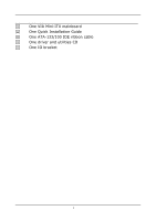
BOX CONTENTS One VIA Mini-ITX mainboard One Quick Installation Guide One ATA-133/100 IDE ribbon cable One driver and utilities CD One IO bracket i - Via EPIA-EN12000EG | User Manual - Page 6
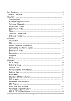
2 Mainboard Layout 5 Back Panel Layout 6 Back Panel Ports 7 Slots 7 Onboard Connectors 8 Onboard Jumpers 8 Chapter 2 9 Installation 9 CPU 10 Memory Module Installation 12 Connecting the Power Supply 13 Back Panel Ports 14 Connectors 17 Jumpers 25 Slots 27 Chapter 3 29 BIOS Setup - Via EPIA-EN12000EG | User Manual - Page 7
Output Connector 51 Integrated Peripherals 52 Super IO Device 54 Power Management Setup 55 Peripheral Activities 57 IRQs Activities 60 PNP 70 Set Supervisor / User Password 71 Save & Exit Setup 73 Exit Without Saving 74 Chapter 4 75 Driver Installation 75 Driver Utilities 76 CD Content - Via EPIA-EN12000EG | User Manual - Page 8
This page is intentionally left blank. iv - Via EPIA-EN12000EG | User Manual - Page 9
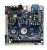
of small, ergonomic, innovative and affordable embedded systems. Through a high level of integration, the Mini-ITX occupy 66% of the size of FlexATX mainboard form factor. The mainboard comes with an embedded VIA Processor, boasting of ultra-low power consumption, cool and quite operation. 1 - Via EPIA-EN12000EG | User Manual - Page 10
Chapter 1 MAINBOARD SPECIFICATIONS CPU • VIA C7 V4 Bus / Eden V4 Bus NanoBGA2 Processor Chipset • VIA CN700 North Bridge • VIA VT8237R-series South Bridge Graphics • Integrated UniChrome™ Pro AGP with MPEG-2 Acceleration Audio • VIA VT1618 8-channel AC'97 Codec Memory • 1 x DDR2 533/400 DIMM slot ( - Via EPIA-EN12000EG | User Manual - Page 11
Video port • 3 x Audio Jacks: line-out, line-in and mic-in (Horizontal, Smart 5.1 Support) Onboard I/O Connectors • 1 x USB pin header for 2 additional USB 2.0 ports • 1 x x Fan connectors (CPU Fan and System Fan) • 1 x LVDS/TTL/DVI (an add-on card is required) • 1 x Front-Panel pin header • 1 x WP pin - Via EPIA-EN12000EG | User Manual - Page 12
Chapter 1 BIOS • • Award BIOS with 4/8Mbit flash memory capacity ACPI2.0, SMBIOS2.1 and DMI2.2 Form Factor • Mini-ITX (6 layers) • 17 cm X 17 cm Note: Due to the hardware limitation, DDR2 SDRAM chips organized as 128Mb x 8 bank cannot be supported by EPIA products with CN700 and CX700M chipsets. - Via EPIA-EN12000EG | User Manual - Page 13
MAINBOARD LAYOUT Specifications 5 - Via EPIA-EN12000EG | User Manual - Page 14
Chapter 1 BACK PANEL LAYOUT PS/2 Mouse COM1 RJ45 LAN RCA/SPDIF PS/2 Keyboard VGA Out USB USB S-Video Line-Out Line-In Microphone 6 - Via EPIA-EN12000EG | User Manual - Page 15
/2 mouse port PS/2 keyboard port RCA port (SPDIF or TV out) RJ45 port USB 2.0 ports VGA port S-Video port SLOTS Port DDR DIMM PCI Description Memory module slot Expansion card slot Specifications Page 13-15 13 13 13 13-14 13-14 13-14 13 13-14 Page 11 26 7 - Via EPIA-EN12000EG | User Manual - Page 16
1 ONBOARD CONNECTORS Connector 1394 ATXPWR COM 2 CPUFAN SIR F_AUDIO F_PANEL IDE 1-2 KBMS LPC/SIR LVDS/TTL/DVI SATA 1-2 SPDIF 1-2 SMBus SYSFAN USB 5-6 TV Description IEEE 1394 connector Power cable connector COM port 2 connector CPU fan connector Fast Infrared Radiation connector Front Audio - Via EPIA-EN12000EG | User Manual - Page 17
CHAPTER 2 Installation This chapter provides you with information about hardware installation procedures. It is recommended to use a grounded wrist strap before handling computer components. Electrostatic discharge (ESD) can damage some components. 9 - Via EPIA-EN12000EG | User Manual - Page 18
Chapter 2 CPU The VIA EPIA-EN Mini-ITX mainboard includes an embedded VIA C7 or Eden V4 Bus Processor. The VIA Eden V4 Bus Processor provides ultra-low power consumption and advanced thermal dissipation properties and features a fanless design. The VIA C7 or Eden V4 Bus Processor requires only a - Via EPIA-EN12000EG | User Manual - Page 19
Installation CPU Fan and System Fan: CPUFAN and SYSFAN The CPUFAN (CPU fan) and SYSFAN (system fan) run on +12V and maintain system cooling. When connecting the wire to the connectors, always be aware that the red wire is the Positive and should be connected to the +12V. The black wire is Ground - Via EPIA-EN12000EG | User Manual - Page 20
MODULE INSTALLATION The VIA EPIA-EN Mini-ITX mainboard provides one 240-pin DIMM slot for DDR2 533/400 SDRAM memory modules and supports the memory size up to 1GB. DIMM DDR SDRAM Module Installation Procedures • Locate the DIMM slot in the motherboard. • Unlock a DIMM slot by pressing the retaining - Via EPIA-EN12000EG | User Manual - Page 21
CONNECTING THE POWER SUPPLY The VIA EPIA-EN Mini-ITX mainboard supports a conventional ATX power supply for the power system. Before inserting the power supply connector, always make sure that all components are installed correctly to ensure that no damage will be caused. ATX 20-Pin Power Connector - Via EPIA-EN12000EG | User Manual - Page 22
Chapter 2 BACK PANEL PORTS The back panel has the following ports: Keyboard and Mouse The green 6-pin connector is for a PS/2 mouse. The purple connector is for a PS/2 keyboard. Serial port: COM 1 The green 9-pin COM 1 port is for pointing devices or other serial devices. VGA Out The blue 15-pin - Via EPIA-EN12000EG | User Manual - Page 23
RJ45 10/100 LAN and USB Connector The mainboard provides a standard RJ-45 and USB 2.0 ports. These ports allow connection to a Local Area Network (LAN) through a network hub and device. S-Video port The black port allows you to connect TV monitor or Svideo device to the mainboard. Installation 15 - Via EPIA-EN12000EG | User Manual - Page 24
5.1 6-channel audio output. You can enable the function by clicking the "Vinyl Audio" icon on your desktop after installing the audio driver. After completing the previous installation, connect the speakers to the 3-jack connectors on the back panel. Shown below are the corresponding connections - Via EPIA-EN12000EG | User Manual - Page 25
CONNECTORS Installation Hard Disk Connectors: IDE1 & IDE2 The mainboard has a 32-bit Enhanced IDE and Ultra DMA 133/100 controller that provides PIO mode 0~4, jumper on the second drive must be set to slave mode. Refer to the drive documentation supplied by the vendor for the jumper settings. 17 - Via EPIA-EN12000EG | User Manual - Page 26
S3 (STR - Suspend To RAM) state, the LED will blink. HDD LED (HD_LED) HDD LED shows the activity of a hard disk drive. Avoid turning the power off when the HDD LED still has a lit. Connect the HDD LED from the system case to this pin. Speaker The speaker from the system - Via EPIA-EN12000EG | User Manual - Page 27
Serial ATA Connectors: SATA1 and SATA2 These next generation connectors support the thin Serial ATA cables for primary internal storage devices. The current Serial ATA interface allows up to 150MB/s data transfer rate, faster than the - Via EPIA-EN12000EG | User Manual - Page 28
I/O interface that provides you fast data transfer rates. The mainboard has one FireWire pin header to provide PC connectivity for a Connector: SIR This pin header is used to connect to an IrDA module. The BIOS settings must be configured to activate the IR function. Pin Signal 1 +5V 2 Key - Via EPIA-EN12000EG | User Manual - Page 29
RTS 9 RI Pin Signal 2 SIN 4 DTR 6 DSR 8 CTS 10 Key COM2 1 2 9 10 Front Panel Audio Connector: F_AUDIO This is an interface for the VIA front panel audio cable that allow convenient connection and control of audio devices. By default, the pins labeled LINE_OUT_R/NEXT_R and the pins - Via EPIA-EN12000EG | User Manual - Page 30
This connector works as the interface to multi display devices. An additional daughter card is required for a certain display support. Daughter cards for LVDS and DVI are currently available respectively. Pin Signal 1 DVID0 3 DVID2 5 DVID4 7 DVID6 9 DVID8 11 DVID10 13 DVIDE 15 DVIVS - Via EPIA-EN12000EG | User Manual - Page 31
: Enable panel VEE power GFPD: Graphic Flat Panel Device signals Installation YPbPr Connector: JTV This pin header is for YPbPr (Component TV output connector) signals. Pin Signal 1 Y 2 GND 3 Pr 4 Key 5 Pb 6 GND JTV 1 2 5 6 KBMS Connector: KBMS The mainboard provides a PS2 pin - Via EPIA-EN12000EG | User Manual - Page 32
Chapter 2 LPC / SIR Connector: JLPC This pin connector is for LPC / SIR devices. Pin Signal 1 LAD1 3 -PCIRSTX 5 LAD0 7 LAD2 9 SERIRQ 11 -LDRQ1 13 +5V 15 +5V 17 IRTX 19 GND Pin Signal 2 LPCCLK1 4 GND 6 SIO_OSC 8 -LFRAME 10 LAD3 12 -EXTSMI 14 +3.3V 16 +3.3V 18 - Via EPIA-EN12000EG | User Manual - Page 33
functions. This section will explain how to change the settings of the mainboard functions using the jumpers. Clear CMOS: CLEAR_CMOS The onboard CMOS RAM stores system configuration data and has an onboard battery power supply. To reset the CMOS settings, set the jumper on pins 2 and 3 while - Via EPIA-EN12000EG | User Manual - Page 34
Chapter 2 BIOS Write Protection: WP This jumper allows you to protect from flashing the BIOS. BIOS WP Write Protection setting: pin1 = /WP & /TBL, pin2 = GND, short 1-2 1 (default) 26 - Via EPIA-EN12000EG | User Manual - Page 35
Component Interconnect: PCI The PCI slot allows you to insert PCI expansion card. When adding or removing expansion card, unplug first the power supply. Read the documentation for the expansion card if any changes to the system are necessary. PCI PCI Interrupt Request Routing The IRQ (interrupt - Via EPIA-EN12000EG | User Manual - Page 36
- Via EPIA-EN12000EG | User Manual - Page 37
CHAPTER 3 BIOS Setup This chapter gives a detailed explanation of the BIOS setup functions. 29 - Via EPIA-EN12000EG | User Manual - Page 38
Chapter 3 ENTERING SETUP Power on the computer and press during the beginning of the boot sequence to enter the BIOS setup menu. If you missed the BIOS setup entry point, you may restart the system and try again. 30 - Via EPIA-EN12000EG | User Manual - Page 39
CONTROL KEYS Keys Up Arrow Down Arrow Left Arrow Right Arrow Enter Escape Page Up / + Page Down / F1 F5 F6 F7 F9 F10 BIOS Setup Description Move to the previous item Move to the next item Move to the item in the left side Move to the item in - Via EPIA-EN12000EG | User Manual - Page 40
The main menu displays all the BIOS setup categories. Use the control keys Up/Down arrow keys to select any item/sub-menu. Description of the selected/highlighted category is displayed at - Via EPIA-EN12000EG | User Manual - Page 41
BIOS Setup GETTING HELP The BIOS setup program provides a "General Help" screen. You can display this screen from any menu/sub-menu by pressing . The help screen displays the keys for using and navigating the BIOS setup. Press to exit the help screen. 33 - Via EPIA-EN12000EG | User Manual - Page 42
Features Integrated Peripherals Power Management Setup PnP / PCI Configurations PC Health Status Frequency / Voltage Control Load Fail-Safe Defaults Load Optimized Defaults Set Supervisor Password Set User Password Save & Exit Setup Exit Without Saving ESC : Quit F9 : Menu in BIOS F10 : Save - Via EPIA-EN12000EG | User Manual - Page 43
for optimal and high performance system operations. Set Supervisor Password Use this menu option to set the BIOS supervisor password. Set User Password Use this menu option to set the BIOS user password. Save & Exit Setup Save BIOS setting changes and exit setup. Exit Without Saving Discard all - Via EPIA-EN12000EG | User Manual - Page 44
20 : 20 [None] [QUANTUM FIREBALLP AS] [None] [None] Item Help Menu Level Change the day, month, year and century Halt On Base Memory Extended Memory Total Memory [All , But Keyboard] 640K 195584K 196608K : Move Enter: Select F5: Previous Values +/-/PU/PD: Value F10: Save F6: Fail-Safe Defaults - Via EPIA-EN12000EG | User Manual - Page 45
IDE DRIVES BIOS Setup IDE HDD Auto-Detection IDE Channel 0 Master Access Mode Capacity if you enter incorrect information in this category. Select "Auto" whenever possible. If you select "Manual", make sure the information is from your hard disk vendor or system manufacturer. Below is a table - Via EPIA-EN12000EG | User Manual - Page 46
FEATURES Phoenix - AwardBIOS CMOS Setup Utility Advanced BIOS Features CPU Feature Hard Disk Boot Priority Virus Warning CPU L1 & L2 Cache Quick Power On Self Test First Boot Device Second Boot Device Third Boot Device Boot Other Device Boot Up NumLock Status Typematic Rate Setting Typematic Rate - Via EPIA-EN12000EG | User Manual - Page 47
Second/Third Boot Device Set the boot device sequence as BIOS attempts to load the disk operating system. Setting LS120 boot device allowed Boot Up NumLock Status Set the NumLock status when the system is powered on. Setting On Off Description Forces keypad to behave as 10-key Forces keypad to - Via EPIA-EN12000EG | User Manual - Page 48
Setup. Setting Setup System Description Password prompt appears only when end users try to run BIOS Setup Password prompt appears every time when the computer is powered on and when end users try to run BIOS Setup APIC Mode Enables APIC (Advanced Programmable Interrupt Controller) functionality - Via EPIA-EN12000EG | User Manual - Page 49
CPU FEATURE BIOS Setup Phoenix - AwardBIOS CMOS Setup Utility CPU Feature Thermal Management TM2 Bus Ratio TM2 Bus VID VIA V4 Fast TRDY VIA V4 Sparse Writes C7 Thermal Monitor C7 CMPXCHG8 C7 NoExecute (NX) C7 TM1/TM2 Working Temp oC C7 TM Overstress Temp oC ODCM ACPI C4 Function [Thermal Monitor - Via EPIA-EN12000EG | User Manual - Page 50
V4 Fast TRDY Settings: [Enabled, Enabled w/wait, Disabled] VIA V4 Sparse Writes Settings: [Enabled, Disabled] C7 Thermal Monitor Settings: [Enabled, Disabled] C7 CMPXCHG8 Settings: [Enabled, Disabled] C7 NoExecute (NX) Settings: [Enabled, Disabled] C7 TM1/TM2 Working Temp ºC This item sets the high - Via EPIA-EN12000EG | User Manual - Page 51
C7 TM Overstress Temp ºC Key in a DEC number. Settings: [Min = 0, Max = 255] BIOS Setup ODCM Enables the ODCM (On Demand Clock Modulation) functionality. Settings: [Enabled, Disabled] ACPI C4 Function Enables the ACPI (Advanced Configuration and Power Management Interface) C4 functionality. - Via EPIA-EN12000EG | User Manual - Page 52
Chapter 3 HARD DISK BOOT PRIORITY Phoenix - AwardBIOS CMOS Setup Utility Hard Disk Boot Priority 1. Pri. Master : 2. Pri. Slave : 3. Sec. Master : 4. Sec. Slave : 5. USB-HDD0 : 6. USB-HDD1 : 7. USB-HDD2 : 8. Bootable Add-In Cards Item Help Menu Level Use < > or < > to select a device, then press - Via EPIA-EN12000EG | User Manual - Page 53
there are display cards on both AGP and PCI slots, configure this item for BIOS to select which one to boot : Move Enter: Select F5: Previous Values +/-/ is used to signal driving current on AGP cards to auto or manual. Settings: [Auto, Manual] AGP Driving Value Key in a HEX number. Settings: [Min - Via EPIA-EN12000EG | User Manual - Page 54
Chapter 3 46 - Via EPIA-EN12000EG | User Manual - Page 55
BIOS Setup Panel Type This setting refers to the native resolution of the display being used with the system. Key in a HEX number. Settings: [Min = 0000, - Via EPIA-EN12000EG | User Manual - Page 56
memory address range dedicated to graphics memory address space. Host cycles that hit the aperture range are forwarded to the AGP without any translation. Settings: [32MB, 64MB, 128MB, 256MB, 512MB, 1G] AGP 2.0 Mode This mainboard supports memory of the processor. Settings: [Enabled, Disabled] 48 - Via EPIA-EN12000EG | User Manual - Page 57
AGP 3.0 Calibration Cycle Settings: [Enabled, Disabled] VGA Share Memory Size Settings: [Disabled, 16M, 32M, 64M] Direct Frame Buffer Settings: [Enabled, Disabled] BIOS Setup 49 - Via EPIA-EN12000EG | User Manual - Page 58
Chapter 3 CPU & PCI BUS CONTROL VLink mode selection VLink 8X Support DRDY_Timing Phoenix - AwardBIOS CMOS Setup Utility CPU & PCI Bus Control [By Auto] [Enabled] [Default] Item Help Menu Level : Move Enter: Select F5: Previous Values +/-/PU/ - Via EPIA-EN12000EG | User Manual - Page 59
- R/G/B SDTV - Pr/Y/Pb Phoenix - AwardBIOS CMOS Setup Utility TV Output Connector [Enabled] [Enabled] [Disabled] [Disabled] [Disabled] [Disabled] Item Help Menu Level BIOS Setup : Move Enter: Select F5: Previous Values +/-/PU/PD: Value F10: Save F6: Fail-Safe Defaults ESC: Exit F1: General F7 - Via EPIA-EN12000EG | User Manual - Page 60
: Exit F1: General F7: Optimized Defaults Help Onboard IDE Channel 1 and 2 The integrated peripheral controller contains an IDE interface with support for two IDE channels. Setting Enabled Disabled Description Activates each channel separately Deactivates IDE channels IDE Prefetch Mode Settings - Via EPIA-EN12000EG | User Manual - Page 61
two SATA plus two PATA hard disk drives Only SATA supports RAID AC'97 Audio Auto allows the mainboard to detect whether an audio device is used. If the device is detected, the onboard VIA AC'97 (Audio Codec'97) controller will be enabled; otherwise, it is disabled. Disable the controller if - Via EPIA-EN12000EG | User Manual - Page 62
Defaults Help Onboard Serial Port 1/2 Sets the base I/O port address and IRQ for the onboard serial ports A and B. Selecting "Auto" allows the BIOS to automatically determine the correct base I/O port address. Port 1 2 Settings Disabled Disabled 3F8 IRQ4 3F8 IRQ4 2F8 IRQ3 2F8 IRQ3 3E8 IRQ4 - Via EPIA-EN12000EG | User Manual - Page 63
contexts. S3/Suspend To RAM (STR) is a power-down state. In this state, power is supplied only to essential components such as main memory and wakeup-capable devices. The system context is saved to main memory, and context is restored from the memory when a "wakeup" event occurs. Depends on the - Via EPIA-EN12000EG | User Manual - Page 64
Off Description System is turned off if power button is pressed for more than four seconds Power button functions as a normal power-on/-off button Run VGABIOS if S3 Resume Select whether to run VGA BIOS if resuming from S3 state. necessary for older VGA drivers. This is only Settings: [Auto, Yes - Via EPIA-EN12000EG | User Manual - Page 65
PERIPHERAL ACTIVITIES BIOS Setup Phoenix - AwardBIOS CMOS Setup Utility Peripherals Activities PS2KB [Hot Key, Password] PS2KB Wakeup from S3/S4/S5 Sets a Hot Key to restore the system from the power saving mode to an active state. Settings: [Disabled, Ctrl+F1, Ctrl+F2, Ctrl+F3, Ctrl+F4, Ctrl+ - Via EPIA-EN12000EG | User Manual - Page 66
management unit to monitor PCI master activities. Settings: [Off, On] PowerOn by PCI Card Enables activity detected from any PCI card to power up the system or resume from a suspended state. Such PCI cards include LAN card, onboard LAN controller, onboard USB ports, etc. Settings: [Disabled, Enabled - Via EPIA-EN12000EG | User Manual - Page 67
BIOS Setup RTC Alarm Resume Sets a scheduled time and/or date to automatically power on the system. Settings: [Disabled, Enabled] Date (of Month) The field specifies the date for "RTC Alarm Resume". Resume Time (hh:mm:ss) The field specifies the time for "RTC Alarm Resume". 59 - Via EPIA-EN12000EG | User Manual - Page 68
Disabled] [Enabled] [Enabled] [Enabled] [Disabled] Item Help Menu Level If you choose Disabled, the power management unit will not monitor any IRQ activities. : Move Enter: Select F5: Previous Values +/-/PU/PD the system will interrupt itself and perform the service required by the IO device. 60 - Via EPIA-EN12000EG | User Manual - Page 69
using a Plug and Play capable operating system. Select No if you need the BIOS to configure non-boot devices. : Move Enter: Select F5: Previous Values +/-/PU as is unless you are an experienced user. PNP OS Installed Setting Yes No Description BIOS will only initialize the PnP cards used - Via EPIA-EN12000EG | User Manual - Page 70
to automatically configure all the Plug-and-Play compatible devices. Setting Auto(ESCD) Manual Description BIOS will automatically assign IRQ, DMA and memory base address fields Unlocks "IRQ Resources" for manual configuration Assign IRQ For VGA/USB Assign IRQ for VGA and USB devices. Settings - Via EPIA-EN12000EG | User Manual - Page 71
IRQ RESOURCES BIOS Setup IRQ-3 assigned to IRQ-4 assigned to IRQ-5 assigned to IRQ-7 : The items are adjustable only when "Resources Controlled By" is set to "Manual." IRQ Resources list IRQ 3/4/5/7/9/10/11/12/14/15 for users to set each IRQ a type depending on the type of device using the - Via EPIA-EN12000EG | User Manual - Page 72
Chapter 3 PC HEALTH STATUS System Temp. CPU Temp. System FAN Speed CPU FAN Speed Vcore 3.3 V +5 V +12 V VBAT (V) 5VSB (V) Phoenix - AwardBIOS CMOS Setup Utility PC Health Status Item Help Menu Level : Move Enter: Select F5: Previous Values +/-/PU/PD: Value F10: Save F6: Fail-Safe Defaults ESC: - Via EPIA-EN12000EG | User Manual - Page 73
BIOS Setup Exit F1: General F7: Optimized Defaults Help DRAM Clock The chipset supports synchronous and asynchronous mode between host clock and DRAM clock frequency. unless you install new memory that has a different performance rating than the original modules. Settings: [Manual, Auto By SPD, - Via EPIA-EN12000EG | User Manual - Page 74
each bank. This field is only available when "DRAM Timing" is set to "Manual". Settings: [Disabled, 2 Bank, 4 Bank, 8 Bank] Precharge to Active ( for setting the length of time it takes to precharge a row in the memory module before the row becomes active. Longer values are safer but may not offer - Via EPIA-EN12000EG | User Manual - Page 75
"Manual". Settings: [2T, 3T, 4T, 5T] BIOS memory modules may not be able to handle lower settings. RDSAIT Mode Settings: [Manual , Auto] RDSAIT Selection Key in a HEX number. Settings: [Min = 0000, Max = 003F] Auto Detect PCI Clk Settings: [Disabled, Enabled] Spread Spectrum When the mainboard - Via EPIA-EN12000EG | User Manual - Page 76
Chapter 3 Settings: [Disabled, 0.20%, 0.25%, 0.35%] 68 - Via EPIA-EN12000EG | User Manual - Page 77
User Password Load Fail-Safe Defaults (YS/aNv)e?& ENxit Setup Exit Without Saving ESC : Quit F9 : Menu in BIOS F10 : Save & Exit Setup : Select Item Load Fail-Safe Defaults BIOS Setup This option is for restoring all the default fail-safe BIOS settings. These values are set by the mainboard - Via EPIA-EN12000EG | User Manual - Page 78
BIOS Features Load Fail-Safe Defaults Advanced Chipset Features Load Optimized Defaults Integrated Peripherals Set Supervisor Password Power Management Setup Set User all the default optimized BIOS settings. The default optimized values are set by the mainboard manufacturer to provide a - Via EPIA-EN12000EG | User Manual - Page 79
changed. When a user password is used, the BIOS Setup program can be accessed but the BIOS settings cannot be changed. To set the password, type the password (up to eight characters in length) and press . The password typed now will clear any previously set password from CMOS memory. The new - Via EPIA-EN12000EG | User Manual - Page 80
Chapter 3 Additionally, when a password is enabled, the BIOS can be set to request the password each time the system is booted. This would prevent unauthorized use of the system. See "Security Option" in the "Advanced BIOS Features" section for more details. 72 - Via EPIA-EN12000EG | User Manual - Page 81
Peripherals Power Management Setup PnP / PCI Configurations PC Health Status Frequency / Voltage Control Load Fail-Safe Defaults Load Optimized Defaults Set Supervisor Password Set User Password SAVE to CMOS & EXIT (YS/aNv)e? & NExit Setup Exit Without Saving ESC : Quit F9 : Menu in BIOS F10 - Via EPIA-EN12000EG | User Manual - Page 82
Peripherals Power Management Setup PnP / PCI Configurations PC Health Status Frequency / Voltage Control Load Fail-Safe Defaults Load Optimized Defaults Set Supervisor Password Set User Password Quit Without Saving (Y/SNa)?ve &NExit Setup Exit Without Saving ESC : Quit F9 : Menu in BIOS F10 - Via EPIA-EN12000EG | User Manual - Page 83
This chapter gives you brief descriptions of each mainboard driver and application. You must install the VIA chipset drivers first before installing other drivers such as audio or VGA drivers. The applications will only function correctly if the necessary drivers are already installed. 75 - Via EPIA-EN12000EG | User Manual - Page 84
utilities and software for enhancing the performance of the mainboard. If the CD is missing from the retail box, please contact the local dealer for the CD. Note: The driver utilities and software are updated from time to time. The latest updated versions are available at http://www.viaembedded.com - Via EPIA-EN12000EG | User Manual - Page 85
the CD into the CD-ROM or DVD-ROM drive. The CD should run automatically after closing the CD-ROM or DVD-ROM drive. The driver utilities and software menu screen should then appear on the screen. If the CD does not run automatically, click on the "Start" button and select - Via EPIA-EN12000EG | User Manual - Page 86
), AGP VxD Driver (provides service routines to your VGA driver and interface directly to hardware, providing fast graphical access), IRQ Routing Miniport Driver (sets the system's PCI IRQ routing sequence) and VIA INF Driver (enables the VIA Power Management function). VIA Graphics Driver: Enhances
-
 1
1 -
 2
2 -
 3
3 -
 4
4 -
 5
5 -
 6
6 -
 7
7 -
8
-
9
-
10
-
11
-
12
-
13
-
14
-
15
-
16
-
17
-
18
-
19
-
20
-
21
-
22
-
23
-
24
-
25
-
26
-
27
-
28
-
29
-
30
-
31
-
32
-
33
-
34
-
35
-
36
-
37
-
38
-
39
-
40
-
41
-
42
-
43
-
44
-
45
-
46
-
47
-
48
-
49
-
50
-
51
-
52
-
53
-
54
-
55
-
56
-
57
-
58
-
59
-
60
-
61
-
62
-
63
-
64
-
65
-
66
-
67
-
68
-
69
-
70
-
71
-
72
-
73
-
74
-
75
-
76
-
77
-
78
-
79
-
80
-
81
-
82
-
83
-
84
-
85
-
86
 |
 |

User’s Manual
EPIA-EN
Version 1.23
January 18, 2012