Via EPIA ME6000 User Manual
Via EPIA ME6000 - VIA Motherboard - Mini ITX Manual
 |
View all Via EPIA ME6000 manuals
Add to My Manuals
Save this manual to your list of manuals |
Via EPIA ME6000 manual content summary:
- Via EPIA ME6000 | User Manual - Page 1
User's Manual EPIA-M Mini-ITX Mainboard P/N: 99-51-012561-14 Version 1.40 December 11, 2003 - Via EPIA ME6000 | User Manual - Page 2
Copyright by VIA Technologies Inc. ("VIA"). No part of this manual may be reproduced or transmitted in any form without express written authorization from VIA. Trademarks All trademarks are the property of their respective holders. PS/2 is a registered trademark of IBM Corporation. Windows 95/98 - Via EPIA ME6000 | User Manual - Page 3
energy and, if not installed and used in accordance with the instruction manual, may cause harmful interference to radio communications. Operation of this equipment equipment. Notice 2 Shielded interface cables and A.C. power cord, if any, must be used in order to comply with the emission limits. - Via EPIA ME6000 | User Manual - Page 4
1. Always read the safety instructions carefully. 2. Keep this User's Manual for future reference. 3. Keep this equipment If any of the following situations arises, get the equipment checked by a service personnel: • The power cord or plug is damaged • Liquid has penetrated into the equipment • - Via EPIA ME6000 | User Manual - Page 5
Box Contents • 1 x VIA Mainboard • 1 x User's Manual • 1 x Floppy Ribbon Cable • 1 x ATA-33/66/100 IDE Ribbon Cable • 1 x Combo Module (2 port USB 2.0 and 2 port IEEE1394) • 1 x Driver Utilities CD v - Via EPIA ME6000 | User Manual - Page 6
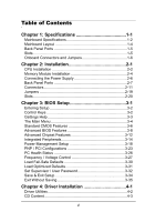
of Contents Chapter 1: Specifications 1-1 Mainboard Specifications 1-2 Mainboard Layout 1-4 Back Panel Ports 1-5 Slots 1-5 Onboard Connectors and Jumpers 1-6 Chapter 2: Installation 2-1 CPU Installation 2-2 Memory Module Installation 2-4 Connecting the Power Supply 2-6 Back Panel Ports - Via EPIA ME6000 | User Manual - Page 7
Appendix A: Smart 5.1 A-1 Intelligent 6-Channel Audio A-2 vii - Via EPIA ME6000 | User Manual - Page 8
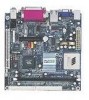
The ultra-compact and highly intergrated VIA EPIA-M Mini-ITX Mainboard is the smallest form factor mainboard specification available today, developed by VIA Technologies, Inc. as part of the company's open industry-wide total connectivity initiative. The mainboard enables the creation of an exciting - Via EPIA ME6000 | User Manual - Page 9
Chapter 1 Mainboard Specifications CPU • VIA C3 / EDEN EBGA Processor (on board) • Enhanced Ball Grid Array Package (EBGA) • Internal L1 128KB and L2 64KB cache memory Chipset • VIA CLE266 North Bridge • VT8235 South Bridge Graphics • Integrated UniChrome graphics with MPEG-2 decoder Audio • VT1616 - Via EPIA ME6000 | User Manual - Page 10
Serial port • 2 USB 2.0 ports; 1 VGA port • 1 RCA port (SPDIF or TV out); 1 S-Video port • 3 Audio jacks: line-out, line-in and mic-in; can be switched to 6 channel output with Smart 5.1 (See Appendix A) BIOS • AwardBIOS with 2 / 4Mbit flash memory Form Factor • 17 cm X 17 cm Mini-ITX (4 layers) 1-3 - Via EPIA ME6000 | User Manual - Page 11
Top: Line-In Middle: Line-Out Bottom: Microphone ATXPWR CPU DIMM CPUFAN SYSFAN IDE1 SPDIF_SEL I2C FIR FDD LVDS COM2 USB 3/4 F_AUDIO 1394_1 1394_2 CIR CMOS BATTERY CLEAR_CMOS BIOS Socket IDE2 CD_IN PCI1 WOL FAN3 F_PANEL Back Panel PS2_MS RJ45 Parallel (LPT1) PS2_KB VGA Out - Via EPIA ME6000 | User Manual - Page 12
Port Audio Jacks COM 1 LPT1 PS2-MS PS2-KB RCA_JACK RJ45 S-VIDEO USB 1-2 VGA Out Description Line-Out, Line-In, Microphone Serial port Parallel Slots Slot DIMM PCI Description Memory module slot Expansion card slot Specifications Page 2-10 2-10 2-9 2-7 2-7 2-8 2-8 2-8 2-8 2-8 Page 2-4 2-20 1-5 - Via EPIA ME6000 | User Manual - Page 13
1394_1 1394_2 ATXPWR CD_IN CIR CLEAR_CMOS COM2 F_AUDIO F_PANEL Fans FDD FIR I2C IDE 1-2 LVDS SPDIF_SEL USB 3/4 WOL Description Connector for first 1394 port Connector for second 1394 port ATX power cable connector Onboard CD audio cable connector Consumer IR connector Jumper to reset CMOS settings - Via EPIA ME6000 | User Manual - Page 14
with information about hardware setup procedures. While installing the mainboard, carefully hold the components and closely follow the installation the following sections: CPU Memory Module Installation Connecting the Power Supply Back Panel Ports Connectors Jumpers Slots 2-2 2-4 2-6 2-7 2-11 - Via EPIA ME6000 | User Manual - Page 15
Chapter 2 CPU The VIA EPIA-M Mini-ITX Mainboard includes an embedded VIA Eden Processor or VIA C3TM E-Series Processor. The CPUFAN (CPU +12V GND FAN3 The VIA C3TM E-Series Processor With low power consumption and advanced thermal dissipation properties, the embedded VIA C3TM E-Series requires only - Via EPIA ME6000 | User Manual - Page 16
consumption and advanced thermal dissipation properties, the VIA Eden Processor features a fanless design. The VIA Eden Processor requires only a heatsink as shown. Installation Warning: This motherboard is not designed to support overclocking. Any attempt to operate beyond product specifications - Via EPIA ME6000 | User Manual - Page 17
Chapter 2 Memory Module Installation The VIA EPIA-M Mini-ITX Mainboard provides one 184-pin DIMM slot for DDR266 SDRAM memory modules. DDR SDRAM Module Installation Procedures 1. Push the white retaining latches at either end of - Via EPIA ME6000 | User Manual - Page 18
Installation Available DDR SDRAM Configurations Refer to the table below for available DDR SDRAM configurations on the mainboard. Slot Memory Module DIMM (Bank 0 & 1) 64MB, 128MB, 256MB, 512MB, 1GB Maximum System Memory Supported Total Memory 64 MB - 1 GB 64 MB - 1 GB 2-5 - Via EPIA ME6000 | User Manual - Page 19
Power Supply The VIA EPIA-M Mini-ITX Mainboard requires an ATX power supply to be connected. Before inserting the power supply connector, always make sure that all components are installed correctly to ensure that no damage will be caused. ATX 20-Pin Power Connector To connect the ATX power supply - Via EPIA ME6000 | User Manual - Page 20
) Installation Line-In Line-Out Microphone PS2_KB VGA Out USB S-Video RCA / SPDIF COM1 Mouse Port: PS2_MS The mainboard provides a standard PS/2 mouse connector for attaching a PS/2 mouse. You can plug a PS/2 mouse directly into this connector. The connector location and pin assignments are - Via EPIA ME6000 | User Manual - Page 21
Chapter 2 VGA Out A DB-15 pin female connector that connects to a VGA monitor. USB Ports The mainboard provides 2 USB 2.0 ports. USB-compatible devices can be plugged directly into these ports. Pin Signal Description 1 VCC + 5V 2 - DATA Negative data channel 3 + DATA Positive data channel - Via EPIA ME6000 | User Manual - Page 22
Installation Parallel Port: LPT1 The mainboard provides a 25-pin female connector for LPT (parallel port). A parallel port is a standard printer port that supports Enhanced Parallel Port (EPP) and Extended Capabilities Parallel Port (ECP) modes. 13 1 25 Pin Signal 1 STROBE 2 DATA0 3 DATA1 - Via EPIA ME6000 | User Manual - Page 23
Chapter 2 Serial Ports: COM1 The mainboard offers two 9-pin male Serial Port connectors COM1. You can attach a serial mouse or other serial devices directly to these ports. 1 5 69 9-Pin Serial Port must be properly configured. Please note that Windows 98 only supports 4-channel audio. 2-10 - Via EPIA ME6000 | User Manual - Page 24
Connectors Installation Hard Disk Connectors: IDE1 & IDE2 The mainboard has a 32-bit Enhanced PCI IDE and Ultra DMA 33/66/100/ 133 controller that the second hard disk drive to slave mode. Please refer to the hard disk documentation supplied by hard disk vendor for the jumper settings. 2-11 - Via EPIA ME6000 | User Manual - Page 25
) or S3 (STR - Suspend To RAM) state, the LED will blink. HDD LED HDD LED shows the activity of a hard disk drive. Avoid turning the power off while HDD LED is lit. Connect the HDD LED from the system case to this pin. SLED The SLED is lit when the system - Via EPIA ME6000 | User Manual - Page 26
IrDA Infrared Module Connector: IR This connector allows you to connect an IrDA Infrared module. You must configure the setting through the BIOS setup to activate the IR function. Pin Signal 1 VCC 2 IRRX1 3 IRRX 4 GND 5 IRTX FIR 1 5 Consumer Infrared Module, PS2 Header: CIR / EXT_KBMS - Via EPIA ME6000 | User Manual - Page 27
pin-header: USB3/4 The mainboard provides 1 front USB pin-header connector, allowing up to 2 additional USB ports. Please plug the USB 2-port module onto this pinheader. Pin Signal 1 VCC 3 USB2 5 USB2 + 7 GND 9 NC Pin Signal 2 VCC 4 USB 3 6 USB 3 + 8 GND 10 GND 2 10 1 9 USB 3/4 Wake-on LAN - Via EPIA ME6000 | User Manual - Page 28
Installation FireWire: IEEE1394 FireWire is a serial I/O interface that provides you fast data transfer rates. There are 2 FireWire ports available. Pin Signal 1 TPA0+ 3 GND 5 TPB0+ 7 1394_VDD 9 GND Pin Signal 2 TPA04 GNF 6 TPB08 1394_VDD 10 2 1 9 COM2 1394_1 2 1394_2 2 1 91 9 COM2: The - Via EPIA ME6000 | User Manual - Page 29
Chapter 2 Floppy Disk Drive Connector: FDD The floppy disk drive connector supports 360K, 720K, 1.2M. 1.44M, and 2.88M floppy disk types. FDD CD Audio Connector: CD_IN This connector is for the CD-ROM audio connector. CD_IN 2-16 - Via EPIA ME6000 | User Manual - Page 30
3V 3 EL-ON 4 SMBCK 5 SMBDT 6 GND I2C 1 6 Installation Front Audio Panel: F_AUDIO This connector allows you to connect a front audio panel to the mainboard. Only the line-out and microphone functions are available for use on the front panel. To connect the front audio cable, first remove - Via EPIA ME6000 | User Manual - Page 31
. This is an option that is added during the manufacturing process. If you would like a mainboard with the LVDS connector, please contact your vendor or sales contact for more information. Pin Signal Pin Signal 1 GFPDE 2 GFPD3 3 GFPD0 4 GFPD4 5 GFPD1 6 GFPD5 7 GFPD2 8 GFPCLK 9 GFPHS - Via EPIA ME6000 | User Manual - Page 32
functions. This section will explain how to change settings for your mainboard's functions through the use of the jumpers. Clear CMOS: CLEAR_CMOS The onboard CMOS RAM stores system configuration data and has an onboard battery power supply. The long-life battery has a lifetime of at least 5 years - Via EPIA ME6000 | User Manual - Page 33
expansion cards, make sure that you unplug the power supply first. Meanwhile, read the documentation for the expansion card to make any necessary hardware or software settings for the expansion card, such as jumpers, switches or BIOS - Via EPIA ME6000 | User Manual - Page 34
Entering Setup 3-2 Control Keys 3-2 Gettings Help 3-3 The Main Menu 3-4 Standard CMOS Features 3-6 Advanced BIOS Features Advanced Chipset Features Integrated Peripherals 3-8 3-12 3-14 Power Management Setup PNP / PCI Configurations PC Health Status 3-18 3-23 3-26 Frequency / Voltage - Via EPIA ME6000 | User Manual - Page 35
Chapter 3 Entering Setup Power on the computer and press Delete straight away to enter the BIOS setup menu. If you missed the BIOS setup entry point, you may restart the system and try again. Control Keys Keys Up Arrow Down Arrow Left Arrow Right Arrow Enter Escape Page - Via EPIA ME6000 | User Manual - Page 36
Main Menu The main menu displays all BIOS setup categories. Use the control keys Up/Down Arrow Keys to Enter to enter the sub-menu. To return from the sub-menu press Esc. General Help: F1 The BIOS setup program provides a General Help screen. You can call up this screen from any menu/sub-menu by - Via EPIA ME6000 | User Manual - Page 37
CMOS Features Use this menu to set basic system configurations. Advanced BIOS Features Use this menu to set the advanced features available on your system. Advanced Chipset Features Use this menu to set chipset specific features and optimize system performance. Integrated Peripherals Use this menu - Via EPIA ME6000 | User Manual - Page 38
and voltage control. Load Fail-Safe Defaults Use this menu option to load the BIOS default settings for minimal and stable system operations. Load Optimized Defaults Use this menu option to load BIOS default settings for optimal and high performance system operations. Set Supervisor Password Use - Via EPIA ME6000 | User Manual - Page 39
, 360K (5.25 in.), 1.2M (5.25 in.), 720K (3.5 in.), 1.44M (3.5 in.), 2.88M (3.5 in.) Halt On Determine the system behaviour if an error is detected at boot. Settings are: All Errors System halts when any error is detected. No Errors System does not halt for any error. All, But Keyboard System - Via EPIA ME6000 | User Manual - Page 40
-menu and the following screen appears: The specifications of your drive must match with the drive table. The hard disk will not work properly if you enter improper information for this category. Select Auto whenever possible. If you select Manual, make sure the information provided is from your - Via EPIA ME6000 | User Manual - Page 41
Chapter 3 Advanced BIOS Features Virus Warning Set the Virus Warning feature for IDE Hard Disk boot sector protection. If the function Settings: Enabled and Disabled Quick Power On Self Test Shorten Power On Self Test (POST) cycle and enable shorter bootup time. Allow BIOS to skip some check items - Via EPIA ME6000 | User Manual - Page 42
/Second/Third Boot Device Set the boot device sequence as BIOS attempts to load the disk operating system. The settings are: Floppy LS120 HDD-0 SCSI CD-ROM HDD-1 HDD-2 HDD-3 ZIP100 USB-FDD USB-ZIP USB-CDROM USB-HDD LAN Disabled The system will boot from floppy drive. The system will boot from LS - Via EPIA ME6000 | User Manual - Page 43
Boot Up NumLock Status Set the NumLock status when the system is powered password, select whether the password is required every time the System boots, or only when you enter Setup. Settings are described below: when the computer is powered on or when end users try to run Setup. Display Full - Via EPIA ME6000 | User Manual - Page 44
BIOS Setup Show Summary Information Show the summary information during the BIOS boot process. Settings: Enabled and Disabled Display Small Logo Show small energy star logo during BIOS bootup process. Settings: Enabled and Disabled 3-11 - Via EPIA ME6000 | User Manual - Page 45
not change these settings unless you are familiar with the chipset. AGP Aperture Size This setting controls how much memory 4MB, 8MB, 16MB, 32MB, 64MB, 128MB, and 256MB AGP Mode (Internal) This mainboard supports the AGP 4x interface. AGP 4x can transfer video data at 1066MB/s and is backward- - Via EPIA ME6000 | User Manual - Page 46
BIOS Setup Select Display Device This setting refers to the type of display being used with the system. Settings resolution of the display being used with the system. Settings: NTSC and PAL CPU Direct Access FB Enable the CPU to directly access the frame buffer. Settings: Enabled and Disabled 3-13 - Via EPIA ME6000 | User Manual - Page 47
Channel 1/2 The integrated peripheral controller contains an IDE interface with support for two IDE channels. Choose Enabled to activate each channel Settings: PCI Slot and AGP Frame Buffer Size This setting instructs the BIOS to reserved the specified amount of memory for the internal video controller. Settings - Via EPIA ME6000 | User Manual - Page 48
This setting allows you to make VIA OnChip LAN enabled or disabled. Settings: Enabled and Disabled USB Keyboard Support Enable USB Keyboard Support for DOS and Windows. Settings: Enabled and Disabled Onboard Lan Boot ROM Enable Onboard Lan Boot ROM for DOS and Windows. Settings: Enabled and Disabled - Via EPIA ME6000 | User Manual - Page 49
address and IRQ for the onboard serial port A/serial port B. Selecting Auto allows BIOS to automatically determine the correct base I/O port address. Settings: Port 1 2 allow the onboard parallel port to support both the ECP and EPP modes simultaneously. Settings: SPP, EPP, ECP, ECP + EPP 3-16 - Via EPIA ME6000 | User Manual - Page 50
BIOS Setup EPP Mode Select EPP (Enhanced Parallel Port) comes in two modes: 1.9 and 1.7. EPP 1.9 is the newer version of the protocol and is backwards compatible - Via EPIA ME6000 | User Manual - Page 51
: S1(POS) S3(STR) S1 & S3 S1/Power On Suspend (POS) is a low power state. In this state, no system context (CPU or chipset) is lost and hardware maintains all system context. S3/Suspend To RAM (STR) is a power-down state. In this state, power is supplied only to essential components such as main - Via EPIA ME6000 | User Manual - Page 52
enters power saving mode, ACPI OS such as Windows XP power button is pressed for more than four seconds. The power button functions as a normal power-on/off buttton. Run VGABIOS if S3 Resume Select whether to run VGA BIOS if resumed from S3 state. This is only necessary for older VGA drivers - Via EPIA ME6000 | User Manual - Page 53
management unit should monitor hard disks and floppy drives activities. Settings: Off and On PCI Master Event Decide whether or not the power management unit should monitor PCI master activities. Settings: Off and On PS2KB Wakeup Select When select Password, please press Page Up or Page Down key - Via EPIA ME6000 | User Manual - Page 54
BIOS Setup PS2KB Wakeup from suspend Select which Hot-Key to wake-up the system from power saving mode. Settings: Disabled, Ctrl+F1, Ctrl+F2, Ctrl+F3, Ctrl+F4, Ctrl+F5, Ctrl+F6, Ctrl+F7, Ctrl+F8, Ctrl+F9, Ctrl+F10, Ctrl+F11, Ctrl+F12, Power, Wake and Any Key USB Resume Decide whether or - Via EPIA ME6000 | User Manual - Page 55
and the following screen appears: Primary INTR Selecting On will cause the system to wake up from power saving modes if activity is detected from any enabled IRQ channels. Settings: Off, On IRQ3~IRQ15 is ready, the system will interrupt itself and perform the service required by the IO device. 3-22 - Via EPIA ME6000 | User Manual - Page 56
settings. PNP OS Installed When set to Yes, BIOS will only initialize the PnP cards used for booting (VGA, IDE, SCSI). The rest of the cards will be initialized by the PnP operating system like Windows® 95 or 98/98SE. When set to No, BIOS will initialize all the PnP cards. Set to Yes - Via EPIA ME6000 | User Manual - Page 57
Chapter 3 Assign IRQ For VGA/USB Assign IRQ for VGA and USB devices. Settings: Disabled and Enabled 3-24 - Via EPIA ME6000 | User Manual - Page 58
BIOS Setup IRQ Resources The items are adjustable only when Resources Controlled By is set to Manual. Press Enter and you will enter the sub-menu of the items. IRQ Resources list IRQ 3/4/5/7/9/10/11/12/14/15 for users to set - Via EPIA ME6000 | User Manual - Page 59
Chapter 3 PC Health Status This section shows the status of your CPU, fan, warning for overall system status. The PC Health Status displays the current status of all of the monitored hardware devices/components such as CPU voltages, temperatures and fan speeds. 3-26 - Via EPIA ME6000 | User Manual - Page 60
Frequency / Voltage Control BIOS Setup DRAM Clock The chipset supports synchronous and asynchronous mode between host clock install new memory that has a different performance rating than the original modules. Settings: Manual and By SPD DRAM CAS Latency This item adjusts the speed it takes for the - Via EPIA ME6000 | User Manual - Page 61
) This field controls the length of time it a row stays active before precharging. Longer values are safer buy may not offer the best performance. This field is only available when DRAM Timing is set to Manual. Settings: 5T, 6T Active to CMD (Trcd) This field is only available when DRAM Timing is - Via EPIA ME6000 | User Manual - Page 62
BIOS Setup DRAM Voltage This field sets the voltage for the memory module. Settings: 2.9V, 2.8V, 2.6V, 2.5V Spread Spectrum When the mainboard's clock generator pulses, the extreme values (spikes) of the pulses creates EMI (Electromagnetic Interference). The Spread Spectrum function reduces the EMI - Via EPIA ME6000 | User Manual - Page 63
Chapter 3 Load Fail-Safe Defaults This option on the main menu allows users to restore all the BIOS settings to the default Fail Safe values. These values are set by the mainboard manufacturer to provide a minimal and stable system. When you select Load-Fail Safe Defaults, a message as below appears - Via EPIA ME6000 | User Manual - Page 64
on the main menu allows users to restore all the BIOS settings to the default Optimized values. The Optimized Defaults are the default values also set by the mainboard manufacturer for both optimized and stable performance of the mainboard. When you select Load Optimized Defaults, a message as below - Via EPIA ME6000 | User Manual - Page 65
the password will be disabled. Once the password is disabled, the system will boot and you can enter Setup without entering any password. When a password has been When a Supervisor password is used, the user can start BIOS Setup program and change the settings of the setup menus. When a User password - Via EPIA ME6000 | User Manual - Page 66
. The setting to determine when the password prompt is required is the Security Option of the Advanced BIOS Features menu. If the Security Option is set to System, the password is required both at boot and at entry to Setup. If set to Setup, password prompt only occurs when trying to enter - Via EPIA ME6000 | User Manual - Page 67
Chapter 3 Save & Exit Setup When you want to quit the Setup menu, you can select this option to save the changes and quit. A message as below will appear on the screen: Entering Y will allow you to quit the Setup Utility and save the user setup changes to RTC CMOS. Entering N will return to the - Via EPIA ME6000 | User Manual - Page 68
Exit Without Saving BIOS Setup When you want to quit the Setup menu, you can select this option to abandon the changes. A message as below will appear on the - Via EPIA ME6000 | User Manual - Page 69
gives you brief descriptions of each mainboard drivers and applications. You must install VIA chipset drivers first before installing other drivers such as audio or VGA drivers. The applications will only function correctly if the necessary drivers are already installed. This chapter includes - Via EPIA ME6000 | User Manual - Page 70
our website (http://www.viaembedded.com/) for the latest updated mainboard driver and utilities. Running the Driver Utilities CD To start using the CD, just simply insert . If the CD does not run automatically, you can run the CD manually by typing "D:\Setup.exe" at Start\Run. (Please note that D: - Via EPIA ME6000 | User Manual - Page 71
(enables the VIA Power Management function). • VIA Graphics Driver: Enhance the onboard VIA graphic chip. • VIA Audio Driver: Enhance the onboard VIA audio chip. • VIA USB 2.0 Driver: Enhance VIA USB 2.0 ports. • VIA LAN Driver: Enhance the onboard VIA LAN chip. • VIA FIR Driver: Support for FIR - Via EPIA ME6000 | User Manual - Page 72
Appendix A Smart 5.1 This chapter gives you brief description of how Smart 5.1 is enabled. This chapter includes the following sections: Intelligent 6-Channel Audio A-2 A-1 - Via EPIA ME6000 | User Manual - Page 73
allows the user to output 6 channel audio directly from the audio jacks on the mainboard, using the traditional line-in and microphone jacks support 6 channel audio. Win98 supports 4 channel only.Please follow the example A and B to enable the Smart 5.1 function, and the examples are based on Windows - Via EPIA ME6000 | User Manual - Page 74
Smart 5.1 2. The panel of [Sounds and Audio Devices Properties] appears and select [Audio] tab. Then press [Advanced] as shown in the picture. 3. Choose [5.1 surround sound speakers] to support the 6 channel function. A-3 - Via EPIA ME6000 | User Manual - Page 75
Appendix A Example B 1. Double click [Sounds and Audio Devices] icon in Control Panel and then select [Audio] tab on the panel as shown below. Press [Volume] button in the [Sound playback] column. 2. [Front Speaker] panel appears and then select [Options] menu to check the item [Advanced Controls]. - Via EPIA ME6000 | User Manual - Page 76
Smart 5.1 3. Then [Front Speaker] panel displays [Advanced] button and press it. 4. Check the item [Smart5.1 Enable] in the panel below. A-5 - Via EPIA ME6000 | User Manual - Page 77
RJ45 Parallel (LPT1) Line-In Line-Out Microphone PS2_KB VGA Out USB S-Video RCA / SPDIF COM1 2-Channel 6-Channel Line-In Line-Out are WIN-DVD v4.0 and Power DVD XP v4.0. Both of them are able to support 5.1 channel. Please follow the instructions below to do the proper settings - Via EPIA ME6000 | User Manual - Page 78
Smart 5.1 2. The panel of Audio Effect appears and click on the lower right corner button as shown in the picture below. 3. The [Setup] panel appears and select [Audio] tab. Then choose the item [6 Channel (5.1 Home Theater)] in the column of [Audio Speaker Configuration]. Finally users can click [ - Via EPIA ME6000 | User Manual - Page 79
Appendix A Power-DVD XP v4.0 1. Open the application and click on the [Configuration] icon shown as the picture below. 2. The panel of Configuration appears and select [Audio]
-
 1
1 -
 2
2 -
 3
3 -
 4
4 -
 5
5 -
 6
6 -
 7
7 -
8
-
9
-
10
-
11
-
12
-
13
-
14
-
15
-
16
-
17
-
18
-
19
-
20
-
21
-
22
-
23
-
24
-
25
-
26
-
27
-
28
-
29
-
30
-
31
-
32
-
33
-
34
-
35
-
36
-
37
-
38
-
39
-
40
-
41
-
42
-
43
-
44
-
45
-
46
-
47
-
48
-
49
-
50
-
51
-
52
-
53
-
54
-
55
-
56
-
57
-
58
-
59
-
60
-
61
-
62
-
63
-
64
-
65
-
66
-
67
-
68
-
69
-
70
-
71
-
72
-
73
-
74
-
75
-
76
-
77
-
78
-
79
 |
 |

User’s Manual
EPIA-M
Mini-ITX Mainboard
P/N: 99-51-012561-14
Version 1.40
December 11, 2003