Via M-700-10E User Manual
Via M-700-10E - VIA Mini ITX Motherboard Manual
 |
UPC - 825529002478
View all Via M-700-10E manuals
Add to My Manuals
Save this manual to your list of manuals |
Via M-700-10E manual content summary:
- Via M-700-10E | User Manual - Page 1
EPIA-M700 User's Manual Version 1.03 September 25, 2008 - Via M-700-10E | User Manual - Page 2
patent or patent rights of VIA Technologies. VIA Technologies makes no warranties, implied digital device, pursuant to part 15 of the FCC rules. in accordance with the instruction manual, may cause harmful user's authority to operate the equipment. Notice 2 Shielded interface cables and A.C. power - Via M-700-10E | User Manual - Page 3
Always read the safety instructions carefully. Keep this User's Manual for future reference. Keep this equipment If any of the following situations arises, get the equipment checked by a service personnel: The power cord or plug is damaged. Liquid has penetrated into the equipment. The equipment - Via M-700-10E | User Manual - Page 4
Memory Module Installation 9 Memory Slot: DDR2 DIMM 9 DDR2 SDRAM Module Installation Procedures 9 Available DDR2 SDRAM Configurations 9 Connecting the Power Supply 10 ATX 20-Pin Power Infrared Module: SIR 15 Serial Port: COM2 15 SPI (Serial Peripheral Interface 15 Buzzer ...15 DVP (Digital - Via M-700-10E | User Manual - Page 5
Power Management Setup 26 PnP/PCI Configurations 26 PC Health Status 27 Frequency/Voltage Control 27 Load Optimized Defaults 27 Set Supervisor Password 27 Set User Slave 30 Advanced BIOS Features 32 Virus Warning...32 CPU L1 & L2 Cache 32 CPU L2 Cache ECC Checking 32 Quick Power On Self- - Via M-700-10E | User Manual - Page 6
BIOS Shadow RAM Cacheable 38 Internal VGA Control 39 VGA Share Memory size 39 Direct Frame Buffer 39 Select Display Device 39 CPU & PCI Bus Control 40 PCI Master 0 WS Write 40 PCI Delay Transaction 40 VIA PWR Management 40 Integrated Peripherals 41 VIA OnChip IDE Device 42 DOM/CF Support - Via M-700-10E | User Manual - Page 7
Auto Restart 49 Wakeup Event Detect 50 PS2KB Wakeup Select 50 PS2KB Wakeup Key Select 50 PS2MS Wakeup Key Select 50 PS2 Keyboard Power On 50 PS2 Mouse Power On 51 PowerOn by PCI Card 51 RTC Alarm Resume 51 Date (of Month)...51 Resume Time (hh : mm : ss 51 PnP/PCI - Via M-700-10E | User Manual - Page 8
56 Load Optimized Defaults 57 Set Supervisor/User Password 58 Set Supervisor ...58 User Password...58 Save & Exit Setup...60 Exit Without Saving 61 CCChhhaaapppttteeerrr444 Driver Installation 63 Driver Utilities ...64 Getting Started ...64 Running the Driver Utilities CD 65 CD Content ...66 - Via M-700-10E | User Manual - Page 9
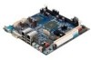
EPIA-M700 User's Manual CHHAAPPTTEERR 1 SPECIFICATIONS The ultra-compact and highly integrated VIA EPIA-M700 uses the MiniITX mainboard form-factor developed by VIA Technologies, Inc. as part of the company's open industry-wide total connectivity initiative. The mainboard enables the creation of an - Via M-700-10E | User Manual - Page 10
EPIA-M700 User's Manual Mainboard Specifications CPU • VIA C7 1.0GHz / 1.5GHz NanoBGA2 processor Chipset • VIA VX800 advanced all-in-one system processor Graphics • Integrated VIA Chrome9™ HC DX9 3D/2D Graphics and Unified Video Decoding Accelerator Audio • VIA VT1708B High Definition Audio codec - Via M-700-10E | User Manual - Page 11
EPIA-M700 User's Manual Back Panel I/O Ports • 1 x Serial port • 2 x RJ45 LAN ports • 1 x DVI-I port • 4 x USB 2.0 ports • 3 x Audio phone jacks: Line-out, Line-in and MIC-in (Horizontal type, Smart 5.1 supported) BIOS • Award BIOS with SPI 4/8Mbit flash memory capacity Form Factor • Mini-ITX (6- - Via M-700-10E | User Manual - Page 12
EPIA-M700 User's Manual Mainboard Layout 4 - Via M-700-10E | User Manual - Page 13
12 0 2 40 1 .8V 1 1 21 EPIA-M700 User's Manual Compact Flash (Bottom side) 5 - Via M-700-10E | User Manual - Page 14
EPIA-M700 User's Manual Back Panel Layout 6 - Via M-700-10E | User Manual - Page 15
EPIA-M700 User's Manual CHHAAPPTTEERR 2 INSTALLATION This chapter provides you with information about hardware installation procedures. It is recommended to use a grounded wrist strap before handling computer components. Electrostatic discharge (ESD) can damage some components. 7 - Via M-700-10E | User Manual - Page 16
EPIA-M700 User's Manual CPU The VIA EPIA-M700 mainboard is packaged with a standard VIA C7 1.5 GHz / 1.0 GHz NanoBGA2 processor. To provide sufficient cooling, VIA C7 1.5 GHz processor requires a heatsink with fan while VIA C7 1.0 GHz requires only a heatsink. 120 240 1.8V 1 121 CPU Fan and - Via M-700-10E | User Manual - Page 17
EPIA-M700 User's Manual Memory Module Installation Memory Slot: DDR2 DIMM The VIA EPIA-M700 mainboard provide one 240-DIMM slot for DDR2 667/533 SDRAM memory modules and supports memory sizes up to 2GB. DDR2 SDRAM Module Installation Procedures • Locate the DIMM slot in the motherboard. • Unlock a - Via M-700-10E | User Manual - Page 18
EPIA-M700 User's Manual Connecting the Power Supply The VIA EPIA-M700 mainboard supports a conventional ATX power supply for the power system. Before inserting the power GND 13 GND 4 +5V 14 Power Supply On 5 GND 15 GND 6 +5V 16 GND 7 GND 17 GND 8 Power Good 18 -5V 9 +5V Standby 19 +5V - Via M-700-10E | User Manual - Page 19
EPIA-M700 User's Manual Back Panel Ports The back panel has the following ports: Gigabit Ethernet RJ-45 Ports Line-In Com Port DVI-I Port USB2.0 Ports Line-Out - Via M-700-10E | User Manual - Page 20
EPIA-M700 User's Manual Connectors IDE Connector: IDE The mainboard has an Ultra DMA 133/100/66/33 controller. You can connect up to two IDE devices in any combination. Pin Signal Pin 1 #IDE_RST 2 3 PD_7 4 5 PD_6 6 7 PD_5 8 9 PD_4 10 11 PD_3 12 13 PD_2 14 15 PD_1 16 17 PD_0 18 - Via M-700-10E | User Manual - Page 21
EPIA-M700 User's Manual SATA Ports These next generation connectors support the thin SATA cables for primary and one USB pin header (allowing up to two additional USB 2.0 ports). Therefore mainboard can support up to six USB 2.0 ports. These ports can be used to connect high-speed USB interface - Via M-700-10E | User Manual - Page 22
EPIA-M700 User's Manual Front Panel Audio: F_Audio This pin header is an interface for the VIA front panel audio cable that allow convenient connection and control of audio devices. Pin Signal 1 MIC2_FR_L 3 MIC2_FR_R 5 LINE_OUT_R 7 FNT_IO_SENSE 9 LINE_OUT_L 11 +12V 13 AGND Pin - Via M-700-10E | User Manual - Page 23
EPIA-M700 User's Manual Serial IrDA Infrared Module: SIR This pin header is used to connect to an IrDA module. The BIOS settings must be configured to activate the IR function. Pin Signal 1 +5V 2 3 This pin header allows you to connect the buzzer speaker. Pin Signal 1 +5V 2 GND 3 GND 4 SPEAK 15 - Via M-700-10E | User Manual - Page 24
EPIA-M700 User's Manual DVP (Digital Video Port) This female connector works the interface to display devices, which allows you to connect an additional daughter cards required for a certain display support. Daughter cards for HDMI and DVI are currently available respectively. Pin Signal Pin 1 - Via M-700-10E | User Manual - Page 25
EPIA-M700 User's Manual VIP (Video Input Port) This pin header is used for CCIR-656/601/transport stream video. Pin Signal Pin Signal 1 GND 2 VCP_D0 3 VCP_D7 4 VCP_D4 5 VCP_D6 6 VCP_D5 7 VCP_HS 8 VCP_D2 9 VCP_D1 10 VCP_D3 11 VCP_VS 12 VCP_CLK 13 DVP1_SPD 14 - 15 DVP1_SPCLK 16 GND - Via M-700-10E | User Manual - Page 26
EPIA-M700 User's Manual Jumpers The mainboard provides jumpers for setting some mainboard functions. This section will explain how to change the settings of the mainboard functions using the jumpers. Clear CMOS Connector: CLEAR_CMOS1 The onboard CMOS RAM stores system configuration data and has an - Via M-700-10E | User Manual - Page 27
EPIA-M700 User's Manual Slots Peripheral Component Interconnect: PCI The PCI slot allows you to insert PCI expansion card. When adding or removing expansion card, unplug first the power supply. Read the documentation for the expansion card if any changes to the system are necessary. PCI Interrupt - Via M-700-10E | User Manual - Page 28
EPIA-M700 User's Manual This page is intentionally left blank. 20 - Via M-700-10E | User Manual - Page 29
EPIA-M700 User's Manual CHHAAPPTTEERR 3 BIOS SETUP This chapter gives a detailed explanation of the BIOS setup functions. 21 - Via M-700-10E | User Manual - Page 30
EPIA-M700 User's Manual Entering the BIOS Setup Menu Power on the computer and press during the beginning of the boot sequence to enter the BIOS setup menu. If you missed the BIOS setup entry point, restart the system and try again. 22 - Via M-700-10E | User Manual - Page 31
EPIA-M700 User's Manual Control Keys Keys Enter Description Move to the previous item Move to the next item Move to the item in the left side Move to - Via M-700-10E | User Manual - Page 32
EPIA-M700 User's Manual Navigating the BIOS Menus The main menu displays all the BIOS setup categories. Use the / and CMOS Setup Utility Standard CMOS Features Advanced BIOS Features Advanced Chipset Features Integrated Peripherals Power Management Setup PnP/PCI Configurations PC Health - Via M-700-10E | User Manual - Page 33
EPIA-M700 User's Manual Getting Help The BIOS setup program provides a "General Help" screen. You can display this screen from any menu/sub-menu by pressing . The help screen displays the keys for using and navigating the BIOS setup. Press to exit the help screen. 25 - Via M-700-10E | User Manual - Page 34
EPIA-M700 User's Manual Main Menu The Main Menu contains twelve setup functions and two exit choices. Use arrow keys to select the items and press to accept or enter Sub-menu. Standard CMOS Features Use this menu to set basic system configurations. Advanced BIOS Features Use this menu to set - Via M-700-10E | User Manual - Page 35
EPIA-M700 User's Manual PC Health Status This menu shows the PC health status. Frequency/Voltage Control Use this menu to set the system frequency and voltage control. Load Optimized Defaults Use this menu option to load BIOS default settings for optimal and high performance system operations. Set - Via M-700-10E | User Manual - Page 36
EPIA-M700 User's Manual Standard CMOS Features Date The date format is [Day, Month Date, Year] Time The time format is [Hour : Minute : Second] Video Settings: [EGA/VGA, CGA - Via M-700-10E | User Manual - Page 37
EPIA-M700 User's Manual IDE Drives IDE Channel 0 Master IDE Channel 0 Slave 29 - Via M-700-10E | User Manual - Page 38
EPIA-M700 User's Manual IDE Channel 1 Master IDE Channel 1 Slave 30 - Via M-700-10E | User Manual - Page 39
EPIA-M700 User's Manual The specifications of your drive must match with the drive table. The hard disk will not work properly if you enter incorrect information in this category. Select "Auto" whenever possible. If you select "Manual", make sure the information is from your hard disk vendor or - Via M-700-10E | User Manual - Page 40
EPIA-M700 User's Manual Advanced BIOS Features Phoenix - AwardBIOS CMOS Setup Utility Advanced BIOS Features CPU Feature Hard Disk Boot Priority Virus Warning CPU L1 & L2 Cache CPU L2 Cache ECC Checking Quick Power On Self Test First Boot Device Second Boot Device Third Boot Device Boot Other - Via M-700-10E | User Manual - Page 41
EPIA-M700 User's Manual Quick Power On Self-Test Shortens Power On Self-Test (POST) cycle to enable shorter boot up time. Settings Disabled Enabled Description Standard Power On Self Test (POST) Shorten Power On Self Test (POST) cycle and boot up time First/Second/Third Boot Device Set the boot - Via M-700-10E | User Manual - Page 42
EPIA-M700 User's Manual Typematic Rate (Chars/Sec) This item sets the rate (characters/second) at which the system retrieves a signal from a depressed key. Settings: [6, 8, 10, 12, 15, 20, 24, 30] Typematic Delay (Msec) This item sets the delay between, when the key was first pressed and when the - Via M-700-10E | User Manual - Page 43
EPIA-M700 User's Manual Summary Screen Show Show summary screen. Settings: [Disabled, Enabled] 35 - Via M-700-10E | User Manual - Page 44
EPIA-M700 User's Manual CPU Features Delay Prior to Thermal Settings: [4 Min, 8 Min, 16 Min, 32 Min] Thermal Management This item sets CPU's thermal control rule to protect CPU from overheat. Settings Thermal Monitor 1 Thermal Monitor 2 Description On-die throtting Ratio & VID transition 36 - Via M-700-10E | User Manual - Page 45
EPIA-M700 User's Manual Hard Disk Boot Priority This is for setting the priority of the hard disk boot order when the "Hard Disk" option is selected in the "[First/Second/Third] Boot Device" menu item. 37 - Via M-700-10E | User Manual - Page 46
EPIA-M700 User's Manual Advanced Chipset Features Caution: The Advanced Chipset Features menu is used for optimizing the chipset functions. Do not change these settings unless you are familiar with the chipset. Memory Hole Settings: [Disabled, 15M - 16M] System BIOS Cacheable Settings: [Disabled, - Via M-700-10E | User Manual - Page 47
EPIA-M700 User's Manual Internal VGA Control VGA Share Memory size This setting allows you to select the amount of system memory that is allocated to the integrated graphics processor. Settings: [Disabled, 64M, 128M, 256M] Direct Frame Buffer Settings: [Disabled, Enabled] Select Display Device - Via M-700-10E | User Manual - Page 48
EPIA-M700 User's Manual CPU & PCI Bus Control PCI Master 0 WS Write Settings: [Enabled, Disabled] PCI Delay Transaction Settings: [Disabled, Enabled] VIA PWR Management Settings: [Disabled, Enabled] 40 - Via M-700-10E | User Manual - Page 49
EPIA-M700 User's Manual Integrated Peripherals 41 - Via M-700-10E | User Manual - Page 50
EPIA-M700 User's Manual VIA OnChip IDE Device DOM/CF Support ATA66 Settings: [Disabled, Enabled] SATA Controller Settings: [Disabled, Enabled] IDE DMA Transfer Access Settings: [Disabled, Enabled] OnChip IDE Channel 1 Settings: [Disabled, Enabled] IDE Prefetch Mode - Via M-700-10E | User Manual - Page 51
EPIA-M700 User's Manual Secondary Master UDMA Settings: [Disabled, Auto] Secondary Slave UDMA Settings: [Disabled, Auto] IDE HDD Block Mode Settings: [Disabled, Enabled] 43 - Via M-700-10E | User Manual - Page 52
EPIA-M700 User's Manual VIA OnChip PCI Device Azalia HDA Controller Settings: [Auto, Disabled] 44 - Via M-700-10E | User Manual - Page 53
EPIA-M700 User's Manual SuperIO Device Onboard Serial Port 1 Settings: [Disabled, 3F8/IRQ4, 2F8/IRQ3, 3E8/IRQ4, 2E8/IRQ3, Auto] Onboard Serial Port 2 Settings: [Disabled, 3F8/IRQ4, 2F8/IRQ3, - Via M-700-10E | User Manual - Page 54
EPIA-M700 User's Manual USB Device Setting USB 1.0 Controller Enable or disable Universal Host Controller Interface for Universal Serial Bus. Settings: , then it operated on high speed mode. USB Keyboard Function Enable or disable Legacy support of USB Keyboard. Settings: [Disabled, Enabled] 46 - Via M-700-10E | User Manual - Page 55
EPIA-M700 User's Manual USB Mouse Function Settings: [Disabled, Enabled] USB Storage Function Enable or disable Legacy support of USB Mass Storage. Settings: [Disabled, Enabled] 47 - Via M-700-10E | User Manual - Page 56
EPIA-M700 User's Manual Power Management Setup ACPI Suspend Type Settings S1(POS) S3(STR) S1 & S3 Description S1/Power On Suspend (POS) is a low power state. In this state, no system context (CPU or chipset) is lost and hardware maintains all system contexts. S3/Suspend To RAM (STR) is a power- - Via M-700-10E | User Manual - Page 57
EPIA-M700 User's Manual Suspend Mode Sets the length of time for a period of inactivity before entering suspend Power button functions as a normal power-on/-off button. Run VGABIOS if S3 Resume Select whether to run VGA BIOS if resuming from S3 state. This is only necessary for older VGA drivers. - Via M-700-10E | User Manual - Page 58
EPIA-M700 User's Manual Wakeup Event Detect PS2KB Wakeup Select When selecting "Password", press - Via M-700-10E | User Manual - Page 59
EPIA-M700 User's Manual PS2 Mouse Power On Settings: [Disabled, Enabled] PowerOn by PCI Card Enables activity detected from any PCI card to power up the system or resume from a suspended state. Such PCI cards include LAN, onboard USB ports, etc. Settings: [By OS, Enabled] RTC Alarm Resume Set a - Via M-700-10E | User Manual - Page 60
EPIA-M700 User's Manual PnP/PCI Configurations Note: This section covers some very technical items and it is strongly recommended to leave the default settings as is unless you are an experienced user ESCD (Extended System Configuration Data) after exiting BIOS Setup if a newly installed PCI card or - Via M-700-10E | User Manual - Page 61
EPIA-M700 User's Manual Resources Controlled By Enable the BIOS to automatically configure all the Plug-and-Play compatible devices. Settings Auto(ESCD) Manual Description BIOS will automatically assign IRQ, DMA and memory base address fields Unlocks "IRQ Resources" for manual configuration PCI - Via M-700-10E | User Manual - Page 62
EPIA-M700 User's Manual PC Health Status The PC Health Status displays the current status of all of the monitored hardware devices/components such as CPU voltages, temperatures and fan speeds. 54 - Via M-700-10E | User Manual - Page 63
EPIA-M700 User's Manual Frequency/Voltage Control DRAM Frequency Settings: [DDR2-400, DDR2-533, DDR-667, SPD] DRAM Channel Mode Settings: [Channel A, Channel A&B, Channel A&C] DDR CAS Latency Control Settings: [ - Via M-700-10E | User Manual - Page 64
EPIA-M700 User's Manual Spread Spectrum When the mainboard's clock generator pulses, the extreme values (spikes) of the pulses create EMI (Electromagnetic Interference). The Spread Spectrum function reduces the - Via M-700-10E | User Manual - Page 65
EPIA-M700 User's Manual Load Optimized Defaults This option is for restoring all the default optimized BIOS settings. The default optimized values are set by the mainboard manufacturer to provide a stable system with optimized performance. Entering "Y" and press to load the - Via M-700-10E | User Manual - Page 66
EPIA-M700 User's Manual Set Supervisor/User Password Set Supervisor User Password This option is for setting a password for entering BIOS Setup. When a password has been set, a password prompt will be displayed whenever BIOS Setup is run. This prevents an unauthorized person from changing any part - Via M-700-10E | User Manual - Page 67
EPIA-M700 User's Manual There are two types of passwords you can set. A supervisor password and a user password. When a supervisor password is used, the BIOS Setup program can be accessed and the BIOS settings can be changed. When a user password is used, the BIOS Setup program can be accessed but - Via M-700-10E | User Manual - Page 68
EPIA-M700 User's Manual Save & Exit Setup Entering "Y" saves any changes made, and exits the program. Entering "N" will cancel the exit request. 60 - Via M-700-10E | User Manual - Page 69
EPIA-M700 User's Manual Exit Without Saving Entering "Y' discards any changes made and exits the program. Entering "N" will cancel the exit request. 61 - Via M-700-10E | User Manual - Page 70
EPIA-M700 User's Manual This page is intentionally left blank. 62 - Via M-700-10E | User Manual - Page 71
EPIA-M700 User's Manual CHHAAPPTTEERR 4 DRIVER INSTALLATION This chapter gives you brief descriptions of each mainboard driver and application. You must install the VIA chipset drivers first before installing other drivers such as VGA drivers. The applications will only function correctly if the - Via M-700-10E | User Manual - Page 72
EPIA-M700 User's Manual Driver Utilities Getting Started The mainboard includes a Driver Utilities CD that contains the drivers and software for enhancing the performance of the mainboard. If the CD is missing from the retail box, please contact the local dealer for the CD. Note: The driver - Via M-700-10E | User Manual - Page 73
EPIA-M700 User's Manual Running the Driver Utilities CD To start using the CD, insert the CD into the CD-ROM or DVD-ROM drive. The CD should run automatically after closing the CD-ROM or DVD-ROM drive. The driver utilities and software menu screen should then appear on the screen. If the CD does not - Via M-700-10E | User Manual - Page 74
EPIA-M700 User's Manual CD Content VIA 4in1 Drivers: Contains VIA ATAPI Vendor Support Driver (enables the performance enhancing bus mastering functions on ATAcapable Hard Disk Drives and ensures IDE device compatibility), AGP VxD Driver (provides service routines to your VGA driver and interface
-
 1
1 -
 2
2 -
 3
3 -
 4
4 -
 5
5 -
 6
6 -
 7
7 -
8
-
9
-
10
-
11
-
12
-
13
-
14
-
15
-
16
-
17
-
18
-
19
-
20
-
21
-
22
-
23
-
24
-
25
-
26
-
27
-
28
-
29
-
30
-
31
-
32
-
33
-
34
-
35
-
36
-
37
-
38
-
39
-
40
-
41
-
42
-
43
-
44
-
45
-
46
-
47
-
48
-
49
-
50
-
51
-
52
-
53
-
54
-
55
-
56
-
57
-
58
-
59
-
60
-
61
-
62
-
63
-
64
-
65
-
66
-
67
-
68
-
69
-
70
-
71
-
72
-
73
-
74
 |
 |

EPIA
EPIA
EPIA
EPIA-M700
M700
M700
M700
User’s Manual
User’s Manual
User’s Manual
User’s Manual
Version 1.03
September 25, 2008