ViewSonic PJ650 Service Manual
ViewSonic PJ650 Manual
 |
View all ViewSonic PJ650 manuals
Add to My Manuals
Save this manual to your list of manuals |
ViewSonic PJ650 manual content summary:
- ViewSonic PJ650 | Service Manual - Page 1
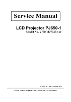
Service Manual LCD Projector PJ650-1 Model No. VPROJ27747-1W (PJ650-1_SM_- Rev. 1 - October 2003) ViewSonic“ 381 Brea Canyon Road, Walnut, California 91789 USA - (800) 888-8583 - ViewSonic PJ650 | Service Manual - Page 2
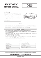
are provided in this Multimedia LCD Projector. Be sure to read cautionary items described in the manual to maintain safety before servicing. Service Warning 1. When replacing the lamp, avoid burns to your fingers. The lamp becomes too hot. 2. Never touch the lamp bulb with a finger or anything else - ViewSonic PJ650 | Service Manual - Page 3
240W 295(W) × 87.5(H) × 237(D) mm 2.7kg (6.04lbs) Operation : 0~35°C Storage : -20~60°C POWER cord × 3 RGB cable × 1 Video/Audio cable × 1 USB mouse cable × 1 Remote control transmitter × 1 Battery × 2 Soft case × 1 CD-ROM (User's guide) × 1 Quick start guide × 1 ViewSonic Corporation 2 PJ650 - ViewSonic PJ650 | Service Manual - Page 4
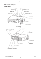
AUDIO IN R and L ports VIDEO IN port Remote sensor Air filter Elevator button S-VIDEO IN port RGB IN 1 and 2 ports AC power inlet STANDBY/ON INPUT KEYSTONE RESET POWERTENPLANP CONTROL port RGB OUT port USB port COMPONENT VIDEO port Elevator button Power switch ViewSonic Corporation 3 PJ650 - ViewSonic PJ650 | Service Manual - Page 5
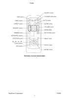
KEYBOARD buttons POSITION button ,,, Cursor buttons ESC button SEARCH button STANDBY/ON button AUTO button BLANK button VOLUME button MUTE button KEYSTONE button MENU button RESET button ENTER button Remote control transmitter ViewSonic Corporation 4 PJ650 - ViewSonic PJ650 | Service Manual - Page 6
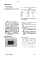
up the projector for about 10 minutes.(Blank white) 2. Set Zoom Wide to Max. And project an image with more than 1m (40 type) in diagonal size. 3. Normalizing the video adjustment. (Press the [MENU] button of the Remote control transmitter to display the MAIN menu, and then press the [RESET] button - ViewSonic PJ650 | Service Manual - Page 7
at the periphery. (When the flicker is about the same across the whole screen, adjust so that the flicker at the center of the screen is somewhat less than elsewhere.) 3. In the same way, use DAC-P - - B: in the Adjustment menu to adjust vertical stripes of B color. ViewSonic Corporation 6 PJ650 - ViewSonic PJ650 | Service Manual - Page 8
RESET] key and select [DEFAULT]. Adjustment procedure 1. First, adjust the G color. 2. Select GAMMA, SUB-CONTRAST, and G: in the Adjust menu. If the background is white solid, press the [ENTER] key on the Remote control brightness white balance of 28 steps is best. ViewSonic Corporation 7 PJ650 - ViewSonic PJ650 | Service Manual - Page 9
reset, press the [RESET] key and select [DEFAULT]. Single tone and monochrome resets cannot be performed. Adjust menu Adjust Tone menu Major adjustment lattice point position �� � � �� � ��� ��� �� � � � �� ��� � �� �� � �� ViewSonic Corporation 8 PJ650 - ViewSonic PJ650 | Service Manual - Page 10
PJ650 Adjustment procedure 1 (when a color differential meter is used) 1. First adjust [MID-L] tone [G:]. 2. Select adjustment point [No.2][G:]. When the background is not [G] monochrome, press the [ENTER] key on the Remote control half as many as [MID-L] tone [G].) ViewSonic Corporation 9 PJ650 - ViewSonic PJ650 | Service Manual - Page 11
PJ650 Adjustment procedure 2 (visual inspection) 1. First adjust [MIN] tone [G:]. 2. Select [No.2] [G:]. If the background is [G] monochrome, press the [ENTER] key on the Remote control �� � ��� ��� �� �� �� �� �� �� ViewSonic Corporation ��� �� �� �� 10 No. 11 deviation - ViewSonic PJ650 | Service Manual - Page 12
PJ650 5. Troubleshooting Check points at trouble shooting � �� �� � �� ��� ViewSonic Corporation 11 PJ650 - ViewSonic PJ650 | Service Manual - Page 13
PJ650 ���� �� ��� ���� ��� �� �� ViewSonic Corporation 12 PJ650 - ViewSonic PJ650 | Service Manual - Page 14
PJ650 ���� ��� �� ��� ViewSonic Corporation 13 PJ650 - ViewSonic PJ650 | Service Manual - Page 15
PJ650 �� ��� ��� ���� �� ��� �� ��� ViewSonic Corporation 14 PJ650 - ViewSonic PJ650 | Service Manual - Page 16
PJ650 �� ��� ��� �� �� ViewSonic Corporation 15 PJ650 - ViewSonic PJ650 | Service Manual - Page 17
PJ650 6. Service points 6-1 Lead free solder [CAUTION] This product uses lead free solder (unleaded) to help preserve the environment. Please read these instructions lead free solder from soldered joints when replacing components. If leaded solder should be REMOTE ViewSonic Corporation 16 PJ650 - ViewSonic PJ650 | Service Manual - Page 18
PJ650 6-2 Cautions when removing the PWB assembly Drive When removing the PWB assembly Drive, there is danger of damaging (CNBAR) connected to POWER UNIT (BALLAST) there is danger of damaging the small PWB connecting cables. POWER UNIT (BALLAST) �� �� ViewSonic Corporation 17 PJ650 - ViewSonic PJ650 | Service Manual - Page 19
batteries. Align and insert the two AA batteries (that came with the projector) according to their plus and minus terminals (as indicated in the remote control). 3. Close the battery cover. Replace the cover in the direction of the arrow and snap it back into place. ViewSonic Corporation 18 PJ650 - ViewSonic PJ650 | Service Manual - Page 20
Lamps" for details.) 1. Turn off the projector, and unplug the power cord. 2. Apply a vacuum cleaner to the top of the air filter cover to clean the air filter. 3. Turn on the projector, and use the menu to reset the filter timer. To reset the air filter timer, from the OPTION menu, select FILTER - ViewSonic PJ650 | Service Manual - Page 21
screwed side of the lamp into the unit. 6. Replace the lamp cover, and tighten the 2 screws firmly to lock it in place. 7. Slowly turn the projector so that the top is facing up. 8. Turn on the projector power, and using the menu, reset the lamp timer. To reset the lamp timer, from the OPTION menu - ViewSonic PJ650 | Service Manual - Page 22
replacing the lamp. Reset the lamp timer always when replacing the lamp. The message functions will not operate properly if the lamp timer is not reset correctly. 2 1, 3 ���� ��� ���� 3 1 ��� 2 1 ViewSonic Corporation 21 PJ650 - ViewSonic PJ650 | Service Manual - Page 23
West. Artifacts on image. Etc. Note 1) The phenomenon at the failure of AUTO adjustment depends on resolution of input source, scene of picture etc. 2) There is no failure above in AUTO with video source through need to search the capture range from input signal itself. ViewSonic Corporation 22 PJ650 - ViewSonic PJ650 | Service Manual - Page 24
screen when the lamp expires or fails. When the lamp does not light, this indicates that lamp is no longer functional and should be replaced. Replace the lamp and do not forget to reset the timer. CLEAN THE AIR FILTER A note of precaution when cleaning the air filter. AFTER CLEANING AIR FILTER - ViewSonic PJ650 | Service Manual - Page 25
turn the power ON again. The green lamp is lighted Simultaneous blink with the red lamp This is a notification that it is time to clean the filter. After cleaning the filter, operate the FILTER TIME portion of the OPTION Menu, and perform reset of the FILTER TIME. Note When the interior portion - ViewSonic PJ650 | Service Manual - Page 26
To display the OSD for "SERVICE MENU" set up. By the control panel By the remote control transmitter 1. Display the menu by the "MENU" button. 2. Select the "OPT." on the menu. 3. Continue press the button " " first, then press the button " " together with "RESET", and hold for 3 seconds - ViewSonic PJ650 | Service Manual - Page 27
PJ650 Setup of Filter time ("ON" or "OFF") 1. Select the "FILTER TIME" on the OSD using button " " by the SERVICE MENU. ���� ��� �� 2.ON : Select the "ON" on the end immediately, use one of buttons except buttons ViewSonic Corporation 26 PJ650 - ViewSonic PJ650 | Service Manual - Page 28
7. Wiring diagram ViewSonic Corporation 27 PJ650 ��� ���� ���� �� ���� ���� ���� PJ650 - ViewSonic PJ650 | Service Manual - Page 29
ViewSonic Corporation 28 ���� PJ650 ���� ���� PJ650 - ViewSonic PJ650 | Service Manual - Page 30
ViewSonic Corporation 29 ���� ��� PJ650 (C3XM4) ���� ���� PJ650 - ViewSonic PJ650 | Service Manual - Page 31
ViewSonic Corporation 30 ���� ���� ���� PJ650 ���� ���� ���� ��� ���� PJ650 - ViewSonic PJ650 | Service Manual - Page 32
ViewSonic Corporation 31 ���� ���� ��� PJ650 PJ650 ���� - ViewSonic PJ650 | Service Manual - Page 33
ViewSonic Corporation 32 PJ650 (C3XM4) ���� ���� �� ���� ���� � � ���� ���� ���� ���� ���� ���� ���� PJ650 - ViewSonic PJ650 | Service Manual - Page 34
PJ650 8. Disassembly diagram M : Meter screw T : Tapping screw � �� ���� �� �� �� � � � �� ViewSonic Corporation 33 PJ650 - ViewSonic PJ650 | Service Manual - Page 35
PJ650 M : Meter screw T : Tapping screw � �� ���� �� � � ���� � � � ���� �� ViewSonic Corporation 34 PJ650 - ViewSonic PJ650 | Service Manual - Page 36
/AUDIO CABLE USB(A-B) CABLE W/CORE REMOTE CONTROL UNIT INSTRUCTION MANUAL CLEANING TOOL FOR DUST SOFT CASE COTTON STICK L70 Power Cord (US type) Power Cord (UK type) Power Cord (Europe type) RGB Cable (computer) Video/Audio cable USB mouse cable Remote Control ViewSonic Corporation 35 PJ650 - ViewSonic PJ650 | Service Manual - Page 37
PJ650 10. RS-232C communication ���� ��� ���� ��� ���� ��� ���� ��� ��� ViewSonic Corporation 36 PJ650 - ViewSonic PJ650 | Service Manual - Page 38
command or data. • Provide an interval of at least 40ms between the response code and any other code. • The projector outputs test data when the power supply is switched ON, and when the lamp is lit. Ignore this data. • Commands are not accepted during warm-up. ViewSonic Corporation 37 PJ650 - ViewSonic PJ650 | Service Manual - Page 39
��� ��� ��� ViewSonic Corporation 38 PJ650 - ViewSonic PJ650 | Service Manual - Page 40
PJ650 Command data chart ���� �� ��� ���� ��� ��� ViewSonic Corporation 39 PJ650 - ViewSonic PJ650 | Service Manual - Page 41
��� ��� ��� ���� ��� ��� ��� ��� ��� ��� ��� ��� ViewSonic Corporation 40 PJ650 - ViewSonic PJ650 | Service Manual - Page 42
PJ650 Command data chart ��� ��� ��� ViewSonic Corporation 41 PJ650 - ViewSonic PJ650 | Service Manual - Page 43
ViewSonic Corporation 42 PJ650 ��� ��� �� ��� ��� ���� 11. Block diagram PJ650 - ViewSonic PJ650 | Service Manual - Page 44
���� ��� ���� ���� ���� ��� � ���� ��� ���� ��� ���� ��� ViewSonic Corporation 43 PJ650 - ViewSonic PJ650 | Service Manual - Page 45
PJ650 13. Basic circuit diagram Parts with hatching are not mounted. � � PWB assembly SENSOR (C3XM4) � � � PWB assembly SWITCH C3XM4) � � � � � � PWB assembly REMOTE (C3XM4) � � ViewSonic Corporation � � 44 � � PJ650 - ViewSonic PJ650 | Service Manual - Page 46
PJ650 Basic circuit diagram list PWB assembly SENSOR PWB assembly DRIVE 5 PWB assembly REMOTE CONTROL PWB assembly DRIVE 6 PWB assembly LIMIT SWITCH PWB assembly DRIVE 7 POWER assembly DRIVE 3 PWB assembly SIGNAL 2 PWB assembly DRIVE 4 PWB assembly SIGNAL 3 ViewSonic Corporation 45 PJ650 - ViewSonic PJ650 | Service Manual - Page 47
6 6 5 5 4 4 3 3 2 2 1 1 Warning For handling of the circuit diagram, refer to the warning on the cover. POWER UNIT (BALLAST) A B C D E F G ViewSonic Corporation PJ650 - ViewSonic PJ650 | Service Manual - Page 48
6 6 5 5 4 4 3 3 2 2 1 Warning For handling of the circuit diagram, refer to the warning on the cover. 1 POWER UNIT (CIRCUIT) A B C D E F G ViewSonic Corporation PJ650 - ViewSonic PJ650 | Service Manual - Page 49
6 6 5 5 4 4 3 3 2 2 1 1 PWB assembly DRIVE 1 A B C D E F G ViewSonic Corporation PJ650 - ViewSonic PJ650 | Service Manual - Page 50
6 6 5 5 4 4 3 3 2 2 1 1 PWB assembly DRIVE 2 A B C D E F G ViewSonic Corporation PJ650 - ViewSonic PJ650 | Service Manual - Page 51
6 6 5 5 4 4 3 3 2 2 1 1 PWB assembly DRIVE 3 A B C D E F G ViewSonic Corporation PJ650 - ViewSonic PJ650 | Service Manual - Page 52
6 6 5 5 4 4 3 3 2 2 1 1 PWB assembly DRIVE 4 A B C D E F G ViewSonic Corporation PJ650 - ViewSonic PJ650 | Service Manual - Page 53
6 6 5 5 4 4 3 3 2 2 1 1 PWB assembly DRIVE 5 A B C D E F G ViewSonic Corporation PJ650 - ViewSonic PJ650 | Service Manual - Page 54
6 6 5 5 4 4 3 3 2 2 1 1 PWB assembly DRIVE 6 A B C D E F G ViewSonic Corporation PJ650 - ViewSonic PJ650 | Service Manual - Page 55
6 6 5 5 4 4 3 3 2 2 1 1 PWB assembly DRIVE 7 A B C D E F G ViewSonic Corporation PJ650 - ViewSonic PJ650 | Service Manual - Page 56
6 6 5 5 4 4 3 3 2 2 1 1 PWB assembly DRIVE 8 A B C D E F G ViewSonic Corporation PJ650 - ViewSonic PJ650 | Service Manual - Page 57
6 6 5 5 4 4 3 3 2 2 1 1 PWB assembly DRIVE 9 A B C D E F G ViewSonic Corporation PJ650 - ViewSonic PJ650 | Service Manual - Page 58
6 6 5 5 4 4 3 3 2 2 1 1 PWB assembly DRIVE 10 A B C D E F G ViewSonic Corporation PJ650 - ViewSonic PJ650 | Service Manual - Page 59
6 6 5 5 4 4 3 3 2 2 1 1 PWB assembly SIGNAL 1 A B C D E F G ViewSonic Corporation PJ650 - ViewSonic PJ650 | Service Manual - Page 60
6 6 5 5 4 4 3 3 2 2 1 1 PWB assembly SIGNAL 2 A B C D E F G ViewSonic Corporation PJ650 - ViewSonic PJ650 | Service Manual - Page 61
6 6 5 5 4 4 3 3 2 2 1 1 PWB assembly SIGNAL 3 A B C D E F G ViewSonic Corporation PJ650 - ViewSonic PJ650 | Service Manual - Page 62
you think about the content after reading PJ650 Service Manual? Unit Excellent Good Fair Bad 1.PRECAUTIONS AND NOTICES 2.SPECIFICATIONS 3.USER OSD MAIN MENU DESCRIPTION 4.ADJUSTMENT PROCEDURE / EDID DATA 5.FACTORY OSD MAIN MENU INSTRUCTION 6.TROUBLE SHOOTING FLOW CHART 7.WAVE FORMS 8.EXPLODED
-
 1
1 -
 2
2 -
 3
3 -
 4
4 -
 5
5 -
 6
6 -
 7
7 -
8
-
9
-
10
-
11
-
12
-
13
-
14
-
15
-
16
-
17
-
18
-
19
-
20
-
21
-
22
-
23
-
24
-
25
-
26
-
27
-
28
-
29
-
30
-
31
-
32
-
33
-
34
-
35
-
36
-
37
-
38
-
39
-
40
-
41
-
42
-
43
-
44
-
45
-
46
-
47
-
48
-
49
-
50
-
51
-
52
-
53
-
54
-
55
-
56
-
57
-
58
-
59
-
60
-
61
-
62
 |
 |

Model No.
V
PROJ27747-1W
Service Manual
LCD Projector PJ
6
5
0
-1
ViewSonic
381 Brea Canyon Road, Walnut, California 91789 USA - (800) 888-8583
(
PJ
65
0
-1
_SM_
- Rev. 1 –
October
200
3
)