ViewSonic PJ650 Service Manual - Page 10
ViewSonic Corporation
 |
View all ViewSonic PJ650 manuals
Add to My Manuals
Save this manual to your list of manuals |
Page 10 highlights
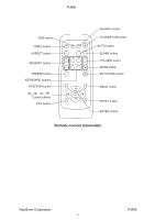
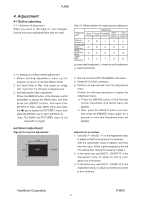
PJ650 Adjustment procedure 1 (when a color differential meter is used) 1. First adjust [MID-L] tone [G:]. 2. Select adjustment point [No.2][G:]. When the background is not [G] monochrome, press the [ENTER] key on the Remote control transmitter to change to solid [G] monochrome. 3. Measure the illumination at adjustment points No. 2, No.3, No.10 and No.11. The values should be: No.2 = Y2 [lx] No.10 = Y10 [lx] No.3 = Y3 [lx] No.11 = Y11 [lx] 4. No.2 and No.3 adjustment point have the average of Y2 and Y3. Y2 = ( Y2 + Y3 ) / 2 ± 2 [%] Y3 = ( Y2 + Y3 ) / 2 ± 2 [%] 5. No.10 and No.11 adjustment point have the average of Y10 and Y11. Y10 = ( Y10 + Y11 ) / 2 ± 2 [%] Y11 = ( Y10 + Y11 ) / 2 ± 2 [%] 6. Then adjust [MID-L] tone [R] and [B]. When the background is [G] monochrome, press the [ENTER] key on the Remote control transmitter to change to solid white. 7. Measure the color coordinates of adjustment point [No.1] and make a note of them. Assume that they are x = x1, y = y1. Note: W h e n t h e C L - 1 0 0 c o l o r a n d c o l o r difference meter is used, the [ ](delta) mode is convenient. When adjustment point [No.1] color coordinate has been selected, set the slide switch on the side to [ ](delta) while holding down the [F] button on the front panel. The measurement shown after this displays the deviation from measurement point 1. 8. Measure the color coordinates of measurement point [No.2] and adjust [No.2][R:] and [B:] so that the coordinates are as follows. x = x1 ± 0.005 , y = y1 ± 0.010 9. Similarly, measure adjustment points [No.3] to [No.17] and adjust their color coordinates starting in order from the small number points. This completes adjustments required for [MIN]. Note: Since excessive correction may lead to a correction data overview during internal calculations, use the following values for reference. [No.2] to [No.5] ± 40 or less [No.6] to [No.9] ± 50 or less [No.10] to [No.13] ± 70 or less [No.14] to [No.17] ± 120 or less 10.T h e n a d j u s t [ M I N ] t o n e [ G ] s o t h a t t h e adjustment data set two times as much as [MID-L] tone [G]. This completes [G] color adjustments. 11. Then adjust [MIN] tone [R] and [B]. Select [No.2] [B:] and press the [ENTER] key on the Remote control transmitter to change to solid white. 12.Measure the color coordinates of adjustment point [No.1] and make a note of them. Assume that they are x = x1, y = y1. 13.N o w m e a s u r e t h e c o l o r c o o r d i n a t e s o f measurement point [No.2] and adjust [No.2][R:] and [B:] so that the coordinates are as follows. x = x1 ± 0.005 , y = y1 ± 0.010 (Target) x = x1 ± 0.020 , y = y1 ± 0.040 14.Similarly, measure adjustment points [No.3] to [No.17] and adjust their color coordinates starting in order from the small number points. This completes [MIN] tone adjustments. 15.Now make similar adjustments for [MID-H] tone. (Adjust [MID-H] tone [G] so that the adjustment data set half as many as [MID-L] tone [G].) 16.Now make similar adjustments for [MAX] tone. (Adjust [MAX] tone [G] so that the adjustment data set half as many as [MID-L] tone [G].) ViewSonic Corporation 9 PJ650
-
 1
1 -
2
-
3
-
4
-
 5
5 -
 6
6 -
 7
7 -
 8
8 -
 9
9 -
 10
10 -
 11
11 -
 12
12 -
 13
13 -
 14
14 -
 15
15 -
16
-
17
-
18
-
19
-
20
-
21
-
22
-
23
-
24
-
25
-
26
-
27
-
28
-
29
-
30
-
31
-
32
-
33
-
34
-
35
-
36
-
37
-
38
-
39
-
40
-
41
-
42
-
43
-
44
-
45
-
46
-
47
-
48
-
49
-
50
-
51
-
52
-
53
-
54
-
55
-
56
-
57
-
58
-
59
-
60
-
61
-
62
 |
 |
