ViewSonic VA902B Service Manual
ViewSonic VA902B - 19" LCD Monitor Manual
 |
UPC - 766907146318
View all ViewSonic VA902B manuals
Add to My Manuals
Save this manual to your list of manuals |
ViewSonic VA902B manual content summary:
- ViewSonic VA902B | Service Manual - Page 1
Service Manual ViewSonic VA902/b Model No. VS10780 19" Color TFT LCD Display (VA902/b_SM Rev. 1a Oct. 2005 ) ViewSonic“ 381 Brea Canyon Road, Walnut, California 91789 USA - (800) 888-8583 - ViewSonic VA902B | Service Manual - Page 2
, in any form or by any means, electronic, mechanical, magnetic, optical, chemical, manual or otherwise, without the prior written permission of ViewSonic Corporation. Disclaimer ViewSonic makes no representations or warranties, either expressed or implied, with respect to the contents hereof and - ViewSonic VA902B | Service Manual - Page 3
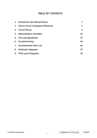
and Safety Notices 1 2. Service Tools & Equipment Required 3 3. Circuit Theory 4 4. Disassembly & Assembly 15 5. Test and Adjustment 19 6. Troubleshooting 24 7. Recommended Parts List 32 8. Schematic Diagrams 42 9. PCB Layout Diagrams 46 ViewSonic Corporation Confidential - Do Not - ViewSonic VA902B | Service Manual - Page 4
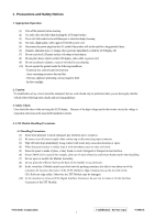
servicing guidelines. 3. Safety Check Care should be taken while servicing this LCD display. Because of the high voltage used in the inverter or removal of the Signal Interface Connector, be sure not to rotate or tilt the Interface Connector of the TFT Module. ViewSonic Corporation Confidential - Do - ViewSonic VA902B | Service Manual - Page 5
an enclosure (LCD monitor housing, for Power Source (IEC60950 or UL1950), or an exemption should be applied for. (14) The LCD module is designed so that the CCFL in it is supplied by a Limited Current Circuit (IEC60950 or UL1950). Do not connect the CCFL to a Hazardous Voltage Circuit. ViewSonic - ViewSonic VA902B | Service Manual - Page 6
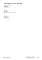
EQUIPMENT REQUIRED 1. SIGNAL GENERATOR 2. MULTIMETER 3. SCREW DRIVER 4. OSCILLOSCOPE 5. Soldering IRON 6. SOLDER 7. VGA Cable (Black, 15pins point to point) 8. Color Analyzer 9. ISP Board 10. EDID Board 11. FOXISP. EXE file 12. EDID program file 13. Power Adapter output 5V/2A ViewSonic Corporation - ViewSonic VA902B | Service Manual - Page 7
Diagram TFT LCD Panel 19" Lamp1 1 Lamp2 2 Transformer1 AOP605L AOP605L OZ9910 Transformer2 Open Protection 4 3 21 On/Off Brightness Power Power Transformer Rectifier & Filter Circuit Block Diagram VGA Connector VGA Input ViewSonic Corporation Confidential - Do Not Copy VA902/b 4 - ViewSonic VA902B | Service Manual - Page 8
loading circuit operated to insure 14V not be increased. 2. 2 Inverter circuit 2.2.1 Low voltage to high voltage circuit 14VDC supplies the power to IC501 through F501; the control signals that BRIGHTNESS and ON/OFF come from I/F board. ON/OFF signal connect to pin8 of IC501 and makes IC501 enabled - ViewSonic VA902B | Service Manual - Page 9
signal IS1 invert U105 #43 outputs reset signal to U104 ( supplied by Monitor self via D104.U103 is an EEPROM IC, which is a kind of memory and used for saving EDID data. 2.3.5 Button Control Button "Key-Power" is defined as power on/off, which is connected to U105 #24 through CN106 #4. ViewSonic - ViewSonic VA902B | Service Manual - Page 10
, and then U105 #43 sends out a HWRESET signal voltage to reset U104, and then monitor goes into stand-by mode. That means hardware power on has been completed. 4.2 Software Power ON/OFF When press power key, U105 #24 recieves low pulse, and sends out "Power on/off" order back to U104, and then - ViewSonic VA902B | Service Manual - Page 11
exit 3 KEY_UP OSD "▲" control to adjust value to increase 4 KEY_POWER DC power on/off control 5 KEY_DOWN OSD "▼" control to adjust value to decrease 6 LED_GREEN Green LED lighting control 7 GND 8 LED_ORANGE Ground Orange LED lighting control ViewSonic Corporation Confidential - Do - ViewSonic VA902B | Service Manual - Page 12
signal of even clock channel (LVDS) minus signal of even channel 3(LVDS) plus signal of even channel 3(LVDS) Ground Ground Ground or Open Ground Power supply (5.0 V) Power supply (5.0 V) Power supply SYNC 14 VSYNC 15 Data clock line (SCL) ViewSonic Corporation Confidential - Do Not Copy VA902/b 9 - ViewSonic VA902B | Service Manual - Page 13
inverter controller IC) Pin No. Symbol I/O Description 1 NDRV4 O Bottom MOSFET gate drive output in dual forward converter 2 PGND High-current power ground 3 NDRV2 O Bottom MOSFET gate drive output in dual forward converter 4 GNDA Low-current signal ground 5 CT I Timing capacitor - ViewSonic VA902B | Service Manual - Page 14
SDA 71 RDZ/SCL 72 INT 73 PWM0 ViewSonic Corporation I/O Description Ground O Digital Output Power Not connected Not connected Not connected Not driving strength I Hardware reset; active high I Crystal Oscillator Input O Crystal Oscillator Output MPLL Power Ground I Analog HSYNC - ViewSonic VA902B | Service Manual - Page 15
LVA0P 113 LVA0M 114 VDDP 115 GND 116 GND 117 VDDC 118 LVB3P ViewSonic Corporation I/O Description O PWM1; 4mA driving strength Not connected Not connected I/O Link Negative LVDS Differential Data Output O Digital Output Power Ground O A-Link Positive LVDS Differential Clock Output - ViewSonic VA902B | Service Manual - Page 16
O B-Link Negative LVDS Differential Data Output O B-Link Positive LVDS Differential Data Output O B-Link Negative LVDS Differential Data Output O Digital Output Power Ground O B-Link Positive LVDS Differential Data Output ViewSonic Corporation Confidential - Do Not Copy VA902/b 13 - ViewSonic VA902B | Service Manual - Page 17
cable detection EEPROM write protection control for DVI EDID Crystal 22.1184MHz In Crystal 22.1184MHz out Sink voltage ground A bi-directional I/O port with alternate function. DC power on/off control OSD "►" control to adjust value to increase OSD "◄" control to adjust value to decrease Selection - ViewSonic VA902B | Service Manual - Page 18
4. Disassembly & Assembly 1. Exploded Diagram and Spare Parts List ViewSonic Corporation Confidential - Do Not Copy VA902/b 15 ViewSonic Corporation Model Title Date Rev: - ViewSonic VA902B | Service Manual - Page 19
2-4 #N/A 502020101710 BRACKET,RIGHT,LE1909 1 2-5 IF BOARD ASS'Y 1 2-6 POWER BOARD ASS'Y 1 2-7 HW-00003169 509146305300 SCREW,PW, ASS'Y 1 COVER,BACK,LE1909(MIDNIGHT GRAY) 1 LOGO PLATE,VIEWSONIC,LE1709(ELLIPSE) 1 SUPPORT VESA LE1709 1 4 C-00003658 714020002500 BASE SUB-ASS'Y - ViewSonic VA902B | Service Manual - Page 20
tape*1) HSD or QDI PANEL*1 BRACKET_L*1 (SCREW,PW,CROSS,M3*5, Ni*4) IF BOARD*1 POWER BOARD*1 FFC CABLE*1 CLIP,WIRE*1 (SCREW,PW,CROSS,M3*5, Ni*4) (BOLT, #4- LENS*1 SUPPORT VESA *1 BACK COVER *1 PLATE BASE *1 BASE COVER *1 NOTE: The arrow is the direction of disassembly. ViewSonic Corporation - ViewSonic VA902B | Service Manual - Page 21
BOARD*1 POWER BOARD*1 FFC CABLE*1 CLIP,WIRE*1 (SCREW,PW,CROSS,M3*5, Ni*5) (BOLT, #4-40x11.8, Ni*2) HSD or QDI PANEL*1 BRACKET_L*1 (SCREW,PW,CROSS,M3*5, Ni*4) LOGO PLATE "VIEWSONIC"*1 SUPPORT LCD MONITOR FINAL ASM NOTE: The arrow is the direction of assembly. ViewSonic Corporation Confidential - Do - ViewSonic VA902B | Service Manual - Page 22
un-display, press these keys to change brightness and contrast Power on or power off the monitor 2. Hot Key Operation CONTROL KEY KEYS user's guide) [1] + [▼] Power Lock [1] + [▲] OSD Lock Remark : All the short cuts function are only available while OSD off ViewSonic Corporation - ViewSonic VA902B | Service Manual - Page 23
3. OSD Control 3.1 OSD table Layer 1 Auto Image Adjust Contrast/Brightness Color Adjust Information Manual Image Adjust Setup Menu Memory Recall Layer 2 Contrast (+ / -) Brightness (+ / -) Srgb 9300K 6500K 5400K User Color H/V Position H Size Fine Tune Sharpness Language Select Resolution Notice - ViewSonic VA902B | Service Manual - Page 24
Resolution Resolution Notice Menu Notice OSD, select Disable ------- 3.5 Factory Mode Introduction When input the signal, press "power key" to turn off the monitor video pattern generator and display 16-gray pattern on the monitor. - Press "Power" to power off the monitor. - Press simultaneously - ViewSonic VA902B | Service Manual - Page 25
RS232 9pin CON on PC D-SUB D-SUB 15PIN 15PIN RS232 9PIN ISP Board Service cable LCD Monitor D-Sub PC VGA output +12V Adapter Normal shipping cable 7.2 Before plug in the power cord, make sure keep "▲" key to be pressed, when power on you can enter ISP mode. 7.3 8051ispwriter.exe will detect - ViewSonic VA902B | Service Manual - Page 26
(640x350 720x400), the detail supported modes and power saving signal. 2. Confirm the above power consumption at each modes State Power Consumption Normal <40W Stand By <1W Power Key Off <1W LED color Green Orange No Chroma signal generator and Power meter AC input: 230V/50Hz ViewSonic - ViewSonic VA902B | Service Manual - Page 27
the problem happen in the digital circuit part. z If you check the H/V position, please use the crosshatch pattern. z This LCM support more than 30 timing modes, if the input timing mode is out of specification, the picture may appears abnormally. z If brightness uneven, repairs Inverter circuit - ViewSonic VA902B | Service Manual - Page 28
2. No Power & Power LED Off No power Check primary rectifier voltage Check pin3 of IC802 voltage about 1V Check circuit if short Check IC802, C805 pin1 of IC802 voltage is 5.8V END Check R803, R807, R824, R825 Check R812, R816, C818 ViewSonic Corporation Confidential - Do Not Copy VA902/b 25 - ViewSonic VA902B | Service Manual - Page 29
END Check Vpin1-2 of IC801 about 1V Check R809, R814 Check ZD801, ZD802, ZD803, D803, D805 Check R809, R814, IC801, R818 Check C815, D806, R812 ViewSonic Corporation Confidential - Do Not Copy VA902/b 26 - ViewSonic VA902B | Service Manual - Page 30
4. Output power is unstable Unstable power Check sampling Circuit Check the R pin voltage of IC803 about 2.5V Check pin1 D806, C815 if short Change D806, C815 Check pin3 of IC802 voltage about 1V ViewSonic Corporation Change R801, R805, R822, R823, R817 END 27 Confidential - Do Not Copy VA902/b - ViewSonic VA902B | Service Manual - Page 31
Is there 14Vdc voltage on pin13 of IC501? No Check power supply Yes Is there high-level voltage on pin8 of IC501? Yes No Is R526 Ok? No No Yes Check I/F board R526 open Connecting the output connector again Is there pulse ViewSonic Corporation Confidential - Do Not Copy VA902/b 28 - ViewSonic VA902B | Service Manual - Page 32
6. Black Screen and backlight turn on ViewSonic Corporation Confidential - Do Not Copy VA902/b 29 - ViewSonic VA902B | Service Manual - Page 33
Screen White Screen LVDS Cable Reinsert OK Workmanship NG Change LVDS Cable OK LVDS Cable NG NG Check VLCD is 5V OK OK Check LVDS signals Panel Fail NG Check Panel-Enable of U105(pin2) is low NG Check the HWRESET of U104 exists NG Check RP101 OK NG OK Check - ViewSonic VA902B | Service Manual - Page 34
of U104 and U105 Workmanship LVDS Cable NG 1.Check X101,C154,C155 2.Check X102,C126,C168 Check ALE/RDZ/ WRZ/AD0/AD1/AD2/ AD3/HWRESET ViewSonic Corporation Confidential - Do Not Copy VA902/b 31 - ViewSonic VA902B | Service Manual - Page 35
16 17 18 Hardware: 19 20 21 22 23 24 25 26 Packing Material: 27 28 Description Power Cord (Australia) Power Cord (British) Power Cord (CCC) Power Cord (CNS) Power Cord (EUROPE) Power Cord (PSE) Power Cord 10A/125V BLK 6FT UL/CSA IF Board Power & Inverter Board Control Board Cover, Hinge, VA902 Base - ViewSonic VA902B | Service Manual - Page 36
SPARE PARTS LIST (VA902b-1) ViewSonic Model Number: VS10780-1W Rev: 1a Serial No. Prefix: PSW Item 1 Accessories: 2 3 4 5 6 7 8 Board Assembly: 9 10 11 Cabinets: 12 13 14 15 Cables: 16 17 18 Hardware: 19 20 21 22 23 24 25 26 Packing Material: 27 28 Description Power Cord (Australia) Power Cord - ViewSonic VA902B | Service Manual - Page 37
17 18 19 20 21 22 23 24 25 26 27 28 29 30 31 32 33 34 35 36 37 38 39 40 41 42 43 44 45 46 47 48 49 50 51 52 53 54 55 56 57 58 59 BOM LIST (VA902-1 for "Hannstar (8ms) Panel") ViewSonic Model Number - ViewSonic VA902B | Service Manual - Page 38
,CARTON(8ms),LE1709,L89xW58mm For VSCN &VSI & VSE &VSE-UK TAPE,WRAPPING TYPE(VIEWSONIC),50mmx75M,LE1709 For VSCN &VSI & VSE &VSE-UK FILM,PROTECTION,UNPRINTED,LE1909/18 For VSCN &VSI & VSE &VSE-UK LABEL,WARRANTY, LE1709 Only for VSCN CARD,WARRANTY, LE1709 Only for VSCN CARD,AFTER SERVICE - ViewSonic VA902B | Service Manual - Page 39
VA902b-1 for "Hannstar (8ms) Panel") ViewSonic Model Number: VS10780-1W Rev: 1a Serial No. Prefix: PSW Item ViewSonic 502080300300 SUPPORT,VESA, LCD PANEL 19" DVI CONN. For VSA HRN LVDS FFC 30P 51 CB-00003662 52 B-00003656 430303000180 790411501000 185mm,ACCX30185KU28MY PCBA,KEYPAD BOARD - ViewSonic VA902B | Service Manual - Page 40
Item ViewSonic P/N 61 #N/A 62 #N/A Ref. P/N 506380002100 506431002050 Description TAPE,WRAPPING TYPE(VIEWSONIC),50mmx75M,LE1709 FILM,PROTECTION,UNPRINTED,LE1909/18 Location For VSA For VSA Qty. 0.0083 ROL 0.1 PC ViewSonic Corporation Confidential Do Not Copy VA902/b 37 - ViewSonic VA902B | Service Manual - Page 41
8. SCHEMATIC DIAGRAM Power Supply C805 C807 100u 450V 33n 400V/ NC ZD802 P6KE200A R804 68R 1/2W C820 2200P Y 1 400V SIZE : 0921341041 A4 TITLE : POWER SUPPLY APPRO BY : CHECK BY : DATE : SHEET 2 2005-06-02 OF 3 Rev : V03 DRAW N BY : ViewSonic Corporation Confidential - Do Not Copy - ViewSonic VA902B | Service Manual - Page 42
3.9K 1% IS3 R507 3.9K 1% T501 EEL-19 22:2600 C524 10P/3KV 2 8 3 5 6 7 C527 5P/3KV C530 6.8n/50V T502 EEL-19 22:2600 2 8 3 5 6 7 C526 TITLE : 0921341041 Inverter A4 CHECK BY : DATE : SHEET 3 2005-07-15 OF 3 Rev : V03 DRAWN BY : ViewSonic Corporation Confidential - - ViewSonic VA902B | Service Manual - Page 43
R170 0 Q102 PMBT3906 VLCD VLCD + C109 100uF/16V C110 0.1/50V R169 22K Q107 PMBT3904 From Power & Inverter CN101 4500-06 1 2 3 4 5 6 VCC5V BRIGHTNESS ON/OFF C111 + C101 0.1/ SHEET 2 2005-06-07 OF 6 Rev : V01 DRAWN BY : ViewSonic Corporation Confidential - Do Not Copy VA902/b 40 - ViewSonic VA902B | Service Manual - Page 44
R125 10K R124 10K VCC5V D104 SN4148 C124 0.1/50V U103 AT24C02N-10SI 1 2 3 4 A0 A1 A2 GND VCC WP SCL SDA 8 7 6 5 ViewSonic Corporation Confidential - Do Not Copy VA902/b 41 ViewSonIinc noLux Document Number : 0921341040 TITLE : VGA_INPUT LE1909 (VA902/bV)A902/b SIZE : A4 APPRO - ViewSonic VA902B | Service Manual - Page 45
0.1/50V C164 100p/50V C163 100p/50V C162 100p/50V GNDC GNDC GNDC GNDC 96 116 19 86 VAA4 FB107 BEAD60OHM C144 C145 10u/16V 0.1/50V Note: U104 pin4,5,7~9,12~17,22~27 : DATE : SHEET 4 2005-06-07 OF 6 Rev : V01 DRAWN BY : ViewSonic Corporation Confidential - Do Not Copy VA902/b 42 - ViewSonic VA902B | Service Manual - Page 46
21 PA0 RXE3+ 22 23 24 25 26 27 VLCD 28 29 VLCD 30 ViewSonic Corporation RXO0RXO1RXO2RXOCRXO3RXE0RXE1RXE2RXECRXE3- VLCD CN104 DUPON2.0mm/NC 24 23 22 21 20 19 18 17 16 15 14 13 12 11 10 9 8 7 6 5 4 3 2 1 RXO0+ RXO1+ RXO2+ RXOC+ RXO3+ RXE0+ RXE1+ RXE2+ RXEC+ RXE3 - ViewSonic VA902B | Service Manual - Page 47
12 P4.3/INT2 P2.0 24 25 P2.1 26 P2.2 P2.3 P2.4 P2.5 27 28 29 P3.7 19 P3.3/INT1 15 P3.1/TXD P3.0/RXD 13 11 22 VSS 20 X2 21 X1 LED_GREEN Q104 PMBT3906 R158 : CHECK BY : DATE : SHEET 6 2005-06-07 OF 6 Rev : V01 DRAWN BY : ViewSonic Corporation Confidential - Do Not Copy VA902/b 44 - ViewSonic VA902B | Service Manual - Page 48
SW TACT MENU/1 SW TACT AUTO/2 SW103 SW TACT POWER SW104 SW TACT DOWN SW105 SW TACT UP LED_GREEN LED_ORANGE KEY_MENU/EXIT KEY_SELECT/AUTO KEY_POWER KEY_DOWN KEY_UP 6 8 2 1 4 5 3 7 CN106 2x4PIN ViewSonic Corporation ViewSonIicnnoLux Document Number : 0921341039 TITLE : KEYPAD LE1909(VA902 - ViewSonic VA902B | Service Manual - Page 49
9. PCB Layout Main board Top layout ViewSonic Corporation Confidential - Do Not Copy VA902/b 46 - ViewSonic VA902B | Service Manual - Page 50
POWER board ViewSonic Corporation Confidential - Do Not Copy VA902/b 47 - ViewSonic VA902B | Service Manual - Page 51
Function Control Description 4. Circuit Description 5. Adjustment Procedure 6. Troubleshooting Flow Chart 7. Recommended Spare Parts List 8. Exploded Diagram and Exploded Parts List 9. Block Diagram 10. Schematic Diagrams 11. PCB Layout Diagrams B. Are you satisfied with this Service Manual
-
 1
1 -
 2
2 -
 3
3 -
 4
4 -
 5
5 -
 6
6 -
 7
7 -
8
-
9
-
10
-
11
-
12
-
13
-
14
-
15
-
16
-
17
-
18
-
19
-
20
-
21
-
22
-
23
-
24
-
25
-
26
-
27
-
28
-
29
-
30
-
31
-
32
-
33
-
34
-
35
-
36
-
37
-
38
-
39
-
40
-
41
-
42
-
43
-
44
-
45
-
46
-
47
-
48
-
49
-
50
-
51
 |
 |
Model No.
VS10780
19
”
Color
TFT LCD Display
Service Manual
ViewSonic VA902/b
ViewSonic
381 Brea Canyon Road, Walnut, California 91789 USA - (800) 888-8583
(VA902/b_SM Rev. 1a Oct. 2005)