Viking VDD5360 VDVE900 - 900 CFM Exterior Power Ventilator - Installation Inst
Viking VDD5360 Manual
 |
View all Viking VDD5360 manuals
Add to My Manuals
Save this manual to your list of manuals |
Viking VDD5360 manual content summary:
- Viking VDD5360 | VDVE900 - 900 CFM Exterior Power Ventilator - Installation Inst - Page 1
VDD5300, CVDD5300, VDD5360, CVDD5360, VDD5450, CVDD5450, VDD5480, CVDD5480 DOWNDRAFT VENTILATORS. READ AND SAVE THESE INSTRUCTIONS WARNING TO REDUCE your distributor. 2. Before servicing or cleaning unit, switch power off at service panel and lock the service disconnecting means to prevent power - Viking VDD5360 | VDVE900 - 900 CFM Exterior Power Ventilator - Installation Inst - Page 2
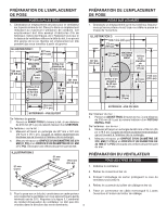
Roof Rafter Roof Rafter Wall Stud Wall Stud PREPARE THE INSTALLATION LOCATION ROOF INSTALLATIONS 1. Locate the blower on the rear slope of the roof. Place it in a location to minimize duct run. The location should be free of obstacles (T.V. leads, electrical lines, etc.). Bear in mind, if the - Viking VDD5360 | VDVE900 - 900 CFM Exterior Power Ventilator - Installation Inst - Page 3
not block grille opening at bottom with trim. It will adversely affect performance of the blower. 10. See downdraft manual for instructions to connect wiring to downdraft electrical panel. 6. Make the electrical connections with the proper connector for the type of wiring being used.Connect white - Viking VDD5360 | VDVE900 - 900 CFM Exterior Power Ventilator - Installation Inst - Page 4
Refer to downdraft ventilator manual for instructions on how to: Locate and cut holes in cabinet. Attach 10" round duct and rough-in plate to downdraft. NOTE: Use duct tape to make ductwork connections secure and air tight. USE AND CARE Disconnect electrical power supply and lock out service panel - Viking VDD5360 | VDVE900 - 900 CFM Exterior Power Ventilator - Installation Inst - Page 5
MODÈLE VDVE900 VENTILATEUR MONTÉ À L'EXTÉRIEUR POUR UTILISATION AVEC LES MODÈLES VDD5300, CVDD5300, VDD5360, CVDD5360, VDD5450, CVDD5450, VDD5480, CVDD5480 VENTILATEURS À TIRAGE VERS LE BAS SEULEMENT VEUILLEZ LIRE CES DIRECTIVES ET LES CONSERVER AVERTISSEMENT AVERTISSEMENT OBSERVEZ LES - Viking VDD5360 | VDVE900 - 900 CFM Exterior Power Ventilator - Installation Inst - Page 6
câble homologué U.L.dans 5. Pour la pose sur un toit plat, construisez un cadre porteur l'ouverture à l'arrière du boîtier de câblage. pour supporter le ventilateur en vous assurant que la pente minimale est de 2/12. Reportez à la figure 2. L'extrémité du conduit d'évacuation du ventilateur ne - Viking VDD5360 | VDVE900 - 900 CFM Exterior Power Ventilator - Installation Inst - Page 7
le couvercle. 8. Assurez-vous que le clapet peut bouger librement avant d'installer le couvercle du boîtier et les vis. 9. Voir le manuel d'instructions pour le ventilateur à tirage vers le bas pour connecter le câblage au panneau électrique le ventilateur à tirage vers le bas. POSE DU VENTILATEUR - Viking VDD5360 | VDVE900 - 900 CFM Exterior Power Ventilator - Installation Inst - Page 8
Faites cheminer les conduits vers l'emplacement du ventilateur à tirage vers le bas. 2. Reportez-vous au guide du ventilateur à tirage vers le bas pour : Localiser et couper des orifices dans l'armoire. Raccordez être huilé ni démonté. VIKING RANGE, LLC GREENWOOD, MISSISSIPPI 38930 USA 8 99045284B - Viking VDD5360 | VDVE900 - 900 CFM Exterior Power Ventilator - Installation Inst - Page 9
NICAMENTE CON EL VENTILADORS DE TIRO DESCENDENTE MODELOS VDD5300, CVDD5300, VDD5360, CVDD5360, VDD5450, CVDD5450, VDD5480, CVDD5480. LEA Y EL TECHO INSTALACIÓN TÍPICA DE MONTAJE EN LA PARED INSTALADOR: Entregue este manual al dueño de la casa DUEÑO DE LA CASA: Las instrucciones de uso y cuidado se - Viking VDD5360 | VDVE900 - 900 CFM Exterior Power Ventilator - Installation Inst - Page 10
Viga del techo Viga del techo Montante de la pared Montante de la pared PREPARE EL LUGAR DE LA INSTALACIÓN INSTALACIONES EN EL TECHO 1. Ubique el ventilador en la pendiente posterior del techo. Colóquelo en un área en la cual minimice la longitud del tramo de conducto. Esta área debe estar libre de - Viking VDD5360 | VDVE900 - 900 CFM Exterior Power Ventilator - Installation Inst - Page 11
BLANCO VERDE CON VERDE 10. Consulte el manual del ventilador de tiro descendente para obtener del regulador de tiro antes de instalar la cubierta y los tornillos. 9. Consulte el manual del ventilador de tiro descendente para obtener instrucciones para conectar el cableado al cuadro elé - Viking VDD5360 | VDVE900 - 900 CFM Exterior Power Ventilator - Installation Inst - Page 12
ventilador. Tienda el conducto hasta el sitio del tiro descendente. 2. Consulte las instrucciones del manual del ventilador de tiro descendente para: Encontrar y cortar los orificios en el gabinete. Conectar ni desarme el motor. VIKING RANGE, LLC GREENWOOD MISSISSIPPI 38930 USA 12 99045284B
-
 1
1 -
 2
2 -
 3
3 -
 4
4 -
 5
5 -
 6
6 -
 7
7 -
8
-
9
-
10
-
11
-
12
 |
 |
1
10" ROUND DUCT
TO
DOWNDRAFT
WARNING
READ
AND
SAVE
THESE
INSTRUCTIONS
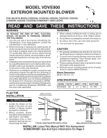
MODEL VDVE900
EXTERIOR MOUNTED
BLOWER
FOR USE WITH MODELS VDD5300, CVDD5300, VDD5360, CVDD5360, VDD5450,
CVDD5450, VDD5480, CVDD5480 DOWNDRAFT VENTILATORS.
TO REDUCE THE RISK OF FIRE, ELECTRIC
SHOCK, OR INJURY TO PERSONS, OBSERVE
THE FOLLOWING:
1.
Use this unit only in the manner intended by the
manufacturer. If you have questions, contact the
manufacturer or your distributor.
2. Before servicing or cleaning unit, switch power off
at service panel and lock the service disconnect-
ing means to prevent power from being switched
on accidentally. When the service disconnecting
means cannot be locked, securely fasten a prom-
inent warning device, such as a tag, to the service
panel.
3.
Installation work and electrical wiring must be done
by a qualified person(s) in accordance with all ap-
plicable codes and standards, including fire-rated
construction codes and standards.
4.
Sufficient air is needed for proper combustion and
exhausting of gases through the flue (chimney) of
fuel burning equipment to prevent backdrafting. Fol-
low the heating equipment manufacturer's guideline
and safety standards such as those published by
the National Fire Protection Association (NFPA),
and the American Society for Heating, Refrigeration
and Air Conditioning Engineers (ASHRAE), and
the local code authorities.
WARNING
CAUTION
1.
For general ventilating use only. Do not use to ex-
haust hazardous or explosive material and vapors.
2.
To avoid motor bearing damage and noisy and/or
unbalanced impellers, keep drywall spray, con-
struction dust, etc. off power unit.
3.
Please read specification label on product for further
information and requirements.
4.
Electrical circuit, including speed control, (if used),
must be rated 6 AMPS minimum.
Blower Dimensions
28.25 x 24.75 x 7.17
PLAN THE
INSTALLATION
1.
Locate the blower so the
length of the duct run and
number of elbows needed
are kept to a minimum.
2. Where possible, blower
should be centered between
wall studs or roof rafters.
3.
Avoid pipes, wires, or other
ductwork that may be run-
ning through the wall.
ALL INSTALLATIONS
MODEL
VOLTS
AMPS
CFM
DUCT SIZE
VDVE900
120
5.7
900
10 " DIA.
SPECIFICATIONS
5. When cutting or drilling into wall, or ceiling, do not
damage electrical wiring or other hidden utilities.
6.
Ducted fans must always be vented to the outdoors.
7.
To reduce risk of fire, use only metal ductwork.
8.
This unit must be grounded.
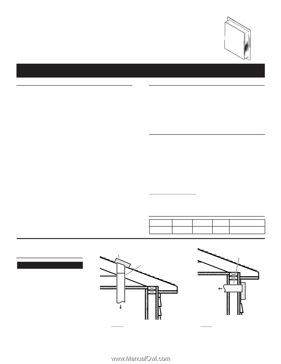
10" ROUND
DUCT
TO
DOWNDRAFT
TYPICAL ROOF MOUNTED INSTALLATION
TYPICAL
WALL MOUNTED INSTALLATION
INSTALLER: Leave This Manual With The Homeowner
HOMEOWNER: Use And Care Information On Page 4
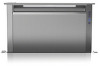
MODEL VDVE900
EXTERIOR BLOWER
MODEL
VDVE900
EXTERIOR
BLOWER