Viking VDD5360 VDVI600 - 600 CFM Interior Power Ventilator - Installation Inst - Page 2
Plan The Installation, Install Flex Blower, In Remote Location, Contents
 |
View all Viking VDD5360 manuals
Add to My Manuals
Save this manual to your list of manuals |
Page 2 highlights
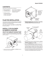
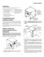
Model VDVI600 CONTENTS These parts are included with your Flex Blower: 2 - blower mounting legs 1 - 6" wide blower panel 2 - 3" wide blower panels 1 - Parts Bag containing: (4) wood screws #10 x .50 (4) blower mount brackets (1) strain relief bushing For use when mounting Flex Blower directly to Downdraft housing. (See Downdraft instruction manual.) (4) MOUNTING BRACKETS attached with 1/4-20 X .50 HEX HEAD SCREWS PLAN THE INSTALLATION If you choose to mount the Flex Blower directly to the Downdraft housing: Remove and discard the adapter plate. Refer to installation instructions in the Downdraft manual. If you choose to mount the Flex Blower in a remote location, (such as the cabinet back, cabinet side, or floor joists) - follow the instructions below. INSTALL FLEX BLOWER IN REMOTE LOCATION NOTE: THE FLEX BLOWER MUST BE INSTALLED WITHIN 4-FEET OF THE DOWNDRAFT'S ELECTRICAL PANEL. The Electrical Panel can be mounted directly to the Downdraft housing - or mounted in a remote location (always within 4-feet of the Flex Blower). (6) MOUNTING BRACKET LOCATIONS 2. Remove the necessary 1/4-20 x .50 hex head screws and attach 4 MOUNTING BRACKETS to the Flex Blower - using 4 of the 6 POSSIBLE BRACKET MOUNTING LOCATIONS. ADAPTER PLATE 8-IN. ROUND DUCT (from downdraft) MOUNTING SCREWS (not included) 8-IN. ROUND DUCT (to roof cap or wall cap) OUTLET (to roof cap or wall cap) INLET (from downdraft) 1. Determine how the 8" round INLET and OUTLET ductwork will connect to the Flex Blower. 3. Mount Flex Blower to back of cabinet, floor joist, or adequate framework (constructed by installer) with appropriate MOUNTING SCREWS (not included). 4. Connect 8" ROUND DUCT from Downdraft housing to Flex Blower inlet and from Flex Blower outlet to roof or wall cap. For best performance: Choose the ducting option which allows the shortest length of ductwork and a minimum number of elbows and transitions. Check location of floor joists, wall studs, electrical wiring or plumbing for possible interference. 5. Use strain relief bushing (provided) to attach Flex Blower wiring to wiring box on Downdraft's electrical panel and make wiring connections. (See Downdraft manual for instructions.) 2
-
 1
1 -
 2
2 -
 3
3 -
 4
4 -
 5
5 -
 6
6 -
 7
7 -
 8
8 -
9
-
10
-
11
-
12
 |
 |
