Vizio L32HDTV10A Service Manual - Page 25
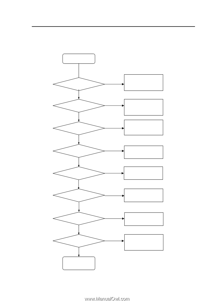
Trouble, Dc-dc, Converter - power board
 |
View all Vizio L32HDTV10A manuals
Add to My Manuals
Save this manual to your list of manuals |
Page 25 highlights
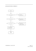
TROUBLE OF DC-DC CONVERTER Start J1 PIN 9,10,11 Yes J1 PIN 2,3,4,5 Yes U7 pin 5 6 7 8 Yes U4 pin2 Yes U6 pin 3 Yes U14 pin2 Yes U5 pin2 U13 pin2 END CONFIDENTIAL - DO NOT COPY The voltage is about + 5V N0 1.Check power board 2.Check power cable connection J1 N0 The voltage is about + 12V while power switch on 1.J1 connection good 2.Check U9 GPIO Pin 3.Check power board The voltage is about +5V while N0 power switch on 1.J1 connection good 2. Check U9 GPIO Pin N0 The voltage is about +3.3V 1.J1 to connection good? 2.Check U4 N0 The voltage is about +9V 1.Check U9 GPIO Pin 2.Check U6 N0 The voltage is about +2.5V while power switch on 1.Check U9 GPIO Pin 2.Check U14 N0 The voltage is about +1.8V 1.Check J1 Connect 2.Check U5&L5 The voltage is about +1.25V while power switch on 1.Check J1 Connect 2.Check U13 Page 10-5 File No. SG-0182
-
 1
1 -
2
-
3
-
4
-
5
-
6
-
7
-
8
-
9
-
10
-
11
-
12
-
13
-
14
-
15
-
16
-
17
-
18
-
19
-
 20
20 -
 21
21 -
 22
22 -
 23
23 -
 24
24 -
 25
25 -
 26
26 -
 27
27 -
 28
28 -
 29
29 -
 30
30 -
31
-
32
-
33
-
34
-
35
-
36
 |
 |