Weider 125 English Manual - Page 5
Assembly
 |
View all Weider 125 manuals
Add to My Manuals
Save this manual to your list of manuals |
Page 5 highlights
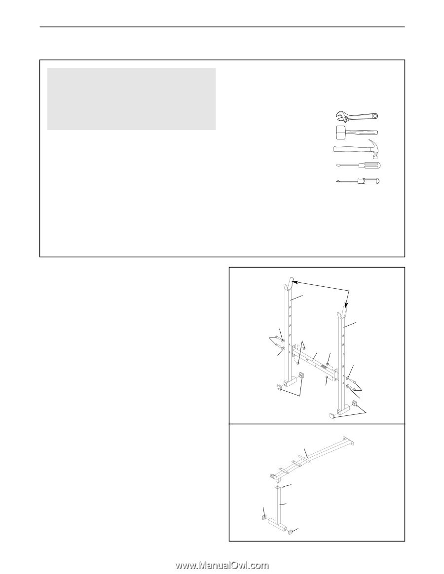
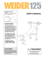
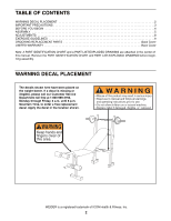
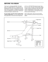
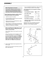
ASSEMBLY Make Things Easier for Yourself This manual is designed to ensure that the weight bench can be assembled successfully by anyone. Most people find that by setting aside plenty of time, assembly will go smoothly. Before beginning assembly, carefully read the following information and instructions: • Assembly requires two people. • For help identifying small parts refer to the PART IDENTIFICATION CHART. • Tighten all parts as you assemble them, unless instructed to do otherwise. • Place all parts in a cleared area and remove the packing materials. Do not dispose of the packing materials until assembly is completed. • As you assemble the weight bench, make sure all parts are oriented as shown in the drawings. The following tools (not included) are required for assembly: • Two adjustable wrenches • One rubber mallet • One hammer • One standard screwdriver • One Phillips screwdriver • Lubricant, such as grease or petroleum jelly, and soapy water. Assembly will be more convenient if you have a socket set, a set of open-end or closed-end wrenches, or a set of ratchet wrenches. 1. Before assembling this weight bench, be sure 1 that you have read and understand the infor- mation in the box above. Tap two 38mm Square Inner Caps (21) into each Upright (1). Attach the Crossbar (3) to the Uprights (1) with four M8 x 55mm Bolts (14), four M8 Washers (12), and four M8 Nylon Locknuts (13). Be sure that the Crossbar and Uprights are oriented as shown. The decal must be facing up and the high side of the weight rests must be on the same side. Do not tighten the Locknuts yet. 2. Tap two 30mm Square Inner Caps (22) into the 2 Front Leg (8). Attach the Front Leg (8) to the Frame (2) with the M10 x 20mm Bolt (17). High Side of Weight Rests 1 12 1 14 13 3 13 12 12 13 21 14 12 21 2 17 22 8 22 5
-
 1
1 -
 2
2 -
 3
3 -
 4
4 -
 5
5 -
 6
6 -
 7
7 -
 8
8 -
 9
9 -
 10
10 -
 11
11 -
12
-
13
-
14
-
15
-
16
 |
 |