Weider 8300 Hard Drive English Manual - Page 11
Weider 8300 Hard Drive Manual
 |
View all Weider 8300 Hard Drive manuals
Add to My Manuals
Save this manual to your list of manuals |
Page 11 highlights
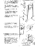
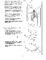
22. Align the holes in the Small "U"-Bracket (21) with the indicated hole in the Front Upright (19). Attach the Small "U"-Bracket to the Front Upright with a 5/16" x 2 3/4" Bolt (122) and 5/16" Nylon Locknut (4). Align one of the three sets of holes in the Adjustment Bracket (22) with the indicated hole in the Front Upright (19). Insert a 5/16" x 2 3/4" Carriage Bolt (113) through the Adjustment Bracket and the Front Upright. Tighten a 5116" Knob (11).onto the Bolt. 23. Press a 1 1/2" Inner Cap (38) into the Seat Frame (32). Attach two Seat Brackets (39) to the Seat Frame (32) with two 1/4" x 2 1/4" Carriage Bolts (40), 1/4" Flat Washers (6), and 1/4" Nylon Locknuts (5). Attach the Press Seat (31) to the Seat Brackets (39) with four 1/4" x 3/4" Screws (7). The narrow end of the Press Seat must be towards the bracket on the Seat Frame (32). 24. Press a 1 1/2" Inner Cap (38) into the Leg Lever (33). Apply grease to a 5/16" x 2 1/4" Bolt (23). Attach the Leg Lever (33) to the Seat Frame (32) with the Bolt and a 5/16" Nylon Locknut (4). Do not overtighten the Nylon Locknut; the Leg Lever must be able to pivot freely. Insert the 5/16" x 2 1/2" Eyebolt (37) through the Leg Lever (33) from the indicated side. Slide a 5/16" Flat Washer (45) onto the Eyebolt, and tighten a 5/16" Nylon Locknut (4) onto the Eyebolt. 22 21 4 . • 122 11---a 30 - ... 19 • .. 22 113 23 31 Narrow End 40 39 7 40 38 : 39 si 7A: 0 32 Bracket 6 / Ce g., 24 4 1 Grease 'I 32 , 23 --33 I !,.c " -----4 e37 - - 45 38 25. Press the four 3/4" Round Caps (36) into the ends of the two Pad Tubes (35). 25 Insert one Pad Tube (35) into the Seat Frame (32) and center it. Slide a Foam Pad (34) onto each end of the Pad Tube. Insert the other Pad Tube into the Leg Lever (33) and center it. Slide a Foam Pad onto each end of the Pad Tube. Align the bracket on the Seat Frame (32) with the indicated tube on the Front Upright (19). Insert a 5/16" x 2 3/4" Carriage Bolt (113) through the Seat Frame and the Front Upright. Tighten a 5/16" Knob (11) onto the Bolt. O 11 ,. 19 .- 11 34 32 34 7' " 36 1"\: i 35 1, 34 16-12 113 / 33 36 * 34
-
 1
1 -
2
-
3
-
4
-
5
-
 6
6 -
 7
7 -
 8
8 -
 9
9 -
 10
10 -
 11
11 -
 12
12 -
 13
13 -
 14
14 -
 15
15 -
 16
16 -
17
-
18
-
19
-
20
-
21
-
22
-
23
-
24
-
25
-
26
-
27
-
28
 |
 |
