Weider 8515 User Manual - Page 10
groove
 |
View all Weider 8515 manuals
Add to My Manuals
Save this manual to your list of manuals |
Page 10 highlights
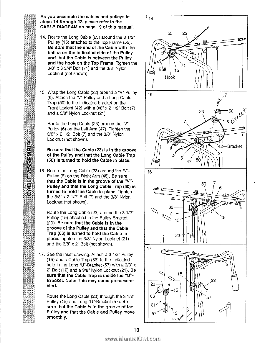
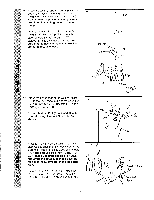
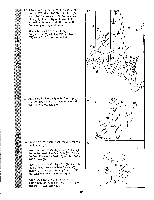
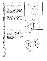
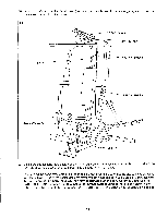
As you assemble the cables and pulleys in steps 14 through 22, please refer to the CABLE DIAGRAM on page 19 of this manual. 14. Route the Long Cable (23) around the 3 1/2" Pulley (15) attached to the Top Frame (55). Be sure that the end of the Cable with the ball is on the indicated side of the Pulley and that the Cable is between the Pulley and the hook on the Top Frame. Tighten the 3/8" x 3 3/4" Bolt (71) and the 3/8" Nylon Locknut (not shown). 15. Wrap the Long Cable (23) around a "V"-Pulley (6). Attach the "V"-Pulley and a Long Cable Trap (50) to the indicated bracket on the Front Upright (42) with a 3/8" x 2 1/2" Bolt (7) and a 3/8" Nylon Locknut (21). Route the Long Cable (23) around the "V"Pulley (6) on the Left Arm (47). Tighten the 3/8" x 2 1/2" Bolt (7) and the 3/8" Nylon Locknut (not shown). Be sure that the Cable (23) is in the groove 2 of the Pulley and that the Long Cable Trap (50) is turned to hold the Cable in place. < 16. Route the Long Cable (23) around the "V"- ILI Pulley (6) on the Right Arm (48). Be sure that the Cable is in the groove of the "V"- CO) Pulley and that the Long Cable Trap (50) is turned to hold the Cable in place. Tighten the 3/8" x 2 1/2" Bolt (7) and the 3/8" Nylon Locknut (not shown). Route the Long Cable (23) around the 3 1/2" Pulley (15) attached to the Pulley Bracket (20). Be sure that the Cable is in the groove of the Pulley and that the Cable Trap (66) is turned to hold the Cable in place. Tighten the 3/8" Nylon Locknut (21) and the 3/8" x 2" Bolt (not shown). 17. See the inset drawing. Attach a 3 1/2" Pulley (15) and a Cable Trap (66) to the indicated hole in the Long "U"-Bracket (57) with a 3/8" x 2" Bolt (12) and a 3/8" Nylon Locknut (21). Be sure that the Cable Trap is inside the "U"Bracket. Note: This may come pre-assembled. Route the Long Cable (23) through the 3 1/2" Pulley (15) and Long "U"-Bracket (57). Be sure that the Cable is in the groove of the Pulley and that the Cable and Pulley move smoothly. 14 55 23 , Ball 71 15 Hook til 15 23 7 ,.,, / 7 r - 50 (c5 6Of 47 5°111 42-Bracket 21 16 50 6 20 66 21 sJ 15 48 23 \ 17 , Q 15 23/a.. . 15 23 66 57 217 ' • • 57 12 / 10
-
 1
1 -
2
-
3
-
4
-
 5
5 -
 6
6 -
 7
7 -
 8
8 -
 9
9 -
 10
10 -
 11
11 -
 12
12 -
 13
13 -
 14
14 -
 15
15 -
16
-
17
-
18
-
19
 |
 |