Weider B121bronze Medallion Bench English Manual - Page 4
Preparation
 |
View all Weider B121bronze Medallion Bench manuals
Add to My Manuals
Save this manual to your list of manuals |
Page 4 highlights
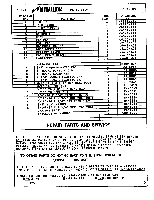
O 0 2 0 H 0 0 .8 0 13 ij 1 STEP 1 - FRAME ASSEMBLY 0 12 11 0 42) 13 0 0 0 *la 0 0 0 Begin by inserting 2 SQUARE PLASTIC CAPS (D) into UPRIGHT (1). Align bolt holes on MAIN FRAME (2) and FRONT SUPPORT (3). Secure with 1 HEX HEAD BOLT (M) and 1 LOCK NUT (J). With UPRIGHT (1) standing, lower u-bracket of MAIN FRAME (2) onto upright crossmember. Align bolt holes and secure with 2 HEX HEAD BOLTS (H) and 2 LOCK NUTS (J). Align bolt holes of UPRIGHT BRACE (11) with the top holes of the hole patterns located on bottom end of UPRIGHT (1) and then through top hole of L-BRACKETS (13). Secure with 2 HEX HEAD BOLTS (R) and '2 LOCK uprrn NUTS (J). Fincer tighten only! Align bottom holes of both L-BRACKETS f1$) and ti) and secure with HEX HEAD BOLTS (H) and LOCK NUTS D. Align bolt hole on MAIN FRAME BRACE (12) with center hole on • UPRIGHT BRACE (11). Secure with HEX HEAD. BOLT (N) and LOCK NUT (J). Align bolt hole on MAIN FRAME BRACE (12) with hole on MAIN FRAME (2) and secure with HEX HEAD BOLT (M) and LOCK NUT (J). Insert 2 SQUARE PLASTIC CAPS (E) into FRONT SUPPORT (3). Tighten all bolts. LOOSEN 10 1 OR 2 TURNS 0 REMOVE 5 STEP 2 - BACKREST PREPARATION Turn BACKREST (5) over to expose work area. Both LONG ANGLE IRONS (10) have been fastened to BACKREST (5) for shipment. One long angle iron must be loosened in order to assemble BACKREST (5) to main frame pivot rod. The lower MACHINE SCREW (K) must be removed while the upper MACHINE SCREW (K) is only loosened. The LONG ANGLE IRON (10) can now swing freely from the lower end of BACKREST (5). 3
-
 1
1 -
 2
2 -
 3
3 -
 4
4 -
 5
5 -
 6
6
 |
 |
