Weider B220 Assembly Instructions - Page 4
crossmember
 |
View all Weider B220 manuals
Add to My Manuals
Save this manual to your list of manuals |
Page 4 highlights
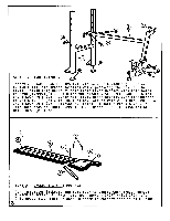
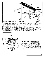
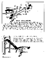
0 0 0 0 2 0 S 0 0 O O 0 • ••• r. 0 • 1 :4 1 O 00 3 N .1* STEP 1 - FRAME ASSEMBLY Insert 2 SQUARE PLASTIC CAPS (M) into base of UPRIGHTS (1). Stand UPRIGHTS (1) into proper position while preparing the rest of the frame. Align bolt holes of Main Frame Lower Bracket with bolt holes on FRONT SUPPORT (3). Join the two pieces with 2 HEX HEAD BOLTS (A) and 2 LOCK NUTS (C). Lower Main Frame Upper Bracket over crossmember on UPRIGHTS (1) and align bolt holes. Secure with 2 HEX HEAD BOLTS (A) and 2 LOCK NUTS (C). Tighten all bolts. Insert 2 PLASTIC CAPS (N) into both ends of FRONT SUPPORT (3). Insert 1 CAP (N) into top of MAIN FRAME (2) tube. 0 0 O SEAT 2 - BACKREST & SEAT PREPARATION Turn assembled Backrest and Seat over to expose work area. Remove 2 MACHINE SCREWS (R) from Seat and remove 1 SHORT ANGLE IRON (7). This preparation must be done in order to connect Seat to Main Frame. 3
-
 1
1 -
 2
2 -
 3
3 -
 4
4 -
 5
5 -
 6
6
 |
 |
