Weider B220 Assembly Instructions - Page 5
Replacement
 |
View all Weider B220 manuals
Add to My Manuals
Save this manual to your list of manuals |
Page 5 highlights
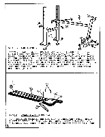
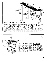
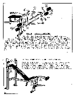
0 0 -.- O 0 P 0 13 0 ir4ot I LI O rr a4 STEP 3 - CONNECTING SEAT TO MAIN FRAME To aid in this assembly, first slide BACKREST ADJUSTMENT BAR (13) into one of the hole patterns on UPRIGHTS (1). Turn BACKREST (4) and SEAT (5) assembly right side up and lower to MAIN FRAME (2). Slide the fastened SHORT ANGLE IRON (7) over the front pivot pin on the MAIN FRAME (2). Align the SEAT ADJUSTMENT T (8) with the proper slot on the main frame and lower through slot. Secure SEAT ADJUSTMENT T (8) by inserting 1 HEX HEAD BOLT (F) through bottom hole and secure with 1 LOCK NUT (E). EYELET PIN (P) is used in the remaining holes of the SEAT ADJUSTMENT T (8) to adjust the desired height of the seat. 0 0 7 0 0 STEP 4 - REPLACEMENT OF SHORT ANGLE IRON To aid in this assembly PIVOT PIN (P) should be placed so that the highest possible position of the Seat is achieved. Slide SHORT ANGLE IRON (7) over pivot pin on SEAT ADJUSTMENT T (8) and front pivot pin on MAIN FRAME (2). Replace 2 MACHINE SCREWS (R) that were removed in Step 2. 4
-
 1
1 -
 2
2 -
 3
3 -
 4
4 -
 5
5 -
 6
6
 |
 |
