Weider Club 16.8st English Manual - Page 18
Seat Assembly
 |
View all Weider Club 16.8st manuals
Add to My Manuals
Save this manual to your list of manuals |
Page 18 highlights
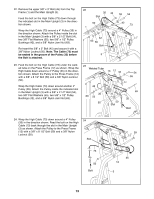
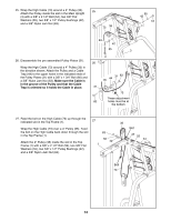
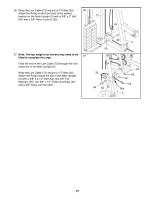
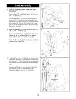
Seat Assembly 38 38. Open the parts bag labeled ÒARM AND SEAT ASSEMBLY.Ó Attach a Seat (13) to the Seat Upright (37) with four 1/4Ó x 3/4Ó Bolts (17). Turn the Adjustment Knob (9) counterclockwise to loosen it. Pull out the Knob as far as possible and slide the Seat Upright (37) into the seat frame on the Main Upright (3). Release the Knob and let it snap into one of the adjustment holes in the Seat Upright. Tighten the Knob fully. 39. Attach the Backrest (41) to the Backrest Frame (15) with four 1/4Ó x 3/4Ó Bolts (17). Press a 3/4Ó Round Inner Cap (34) into each end of the pad bar on the Backrest Frame (15). Slide a Foam Pad (30) onto each end of the pad bar. Press 1Ó x 2Ó Inner Caps (43) into the top and bottom of the Backrest Frame (15). 37 17 9 39 43 17 15 17 13 17 Adjustment Holes 3 41 34 30 40. Locate the Adjustment Knob (9) on the backrest tube of the Main Upright (3). Turn the Knob counterclockwise to loosen it. Pull out the Knob as far as possible and slide the Backrest Frame (15) into the backrest tube. Release the Adjustment Knob (9) and let the Knob snap into one of the adjustment holes on the Backrest Frame (15). Tighten the Knob fully. 34 30 40 Backrest Tube 43 Pad Bar 3 15 9 Adjustment Holes 18
-
 1
1 -
2
-
3
-
4
-
5
-
6
-
7
-
8
-
9
-
10
-
11
-
12
-
 13
13 -
 14
14 -
 15
15 -
 16
16 -
 17
17 -
 18
18 -
 19
19 -
 20
20 -
 21
21 -
 22
22 -
 23
23 -
24
-
25
-
26
-
27
-
28
-
29
-
30
-
31
-
32
-
33
 |
 |
