Weider Ultramax 1033 Owners Manual - Page 6
Weider Ultramax 1033 Manual
 |
View all Weider Ultramax 1033 manuals
Add to My Manuals
Save this manual to your list of manuals |
Page 6 highlights
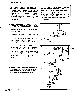
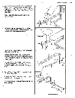
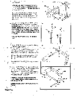
Curl Tube (10). 8 46-Lubricate Irisert the Curl Tube (10) through the indicated hole in the Leg Lever (8). Secure the Curl Tube with the 8mm Eye Bolt (34), the 8mm Nut (56) and an 8mm Locknut (30). Apply lubricant to the 10mm x 55mm Bolt (46). • Attach the Leg Lever (8) to the Main Frame (3) with the Bolt and a 10mm Locknut (45). Do not overtighten the Locimut.The Leg Lever must pivot freely. 34 a 45 56 3 $ a 30 40 10 a 54 9. Insert one of the Weight Rests (24) into the "H"Frame (1). Raise the Weight Rest to the desired 9 height, and align one of the four small holes in the Weight Rest with the small hole in the "H"-Frame. Insert a Locking Pin (52) through the "H"-Frame and the Weight Rest. Rotate the Locking Pin to the locked position, with the Locking Pin clipped to the "H"-Frame. Attach the other Weight Rest (24) in the same manner. 5 1 24 24 52 6- 10. Press al 1/2" Square Cap (53) into the indicated end of the Right Arm (20). 10 Insert a 9" Pad Tube (22) into the indicated hole in the Right Arm (20). Math the Pad Tube with an 8mm x 45mm Screw (42) and an 8mm Locknut (30). Press a V Round Cap (40) into the end of the 9" Pad Tube (22). Slide a Foam Pad (11) onto the Pad Tube. Assemble the Left Arm (21) (not shown) in the same manner. 40 0 11 . 11. Insert a 10 1/2" Weight Tube (23) into the indicated hole in the Right Arm (20). Attach the Weight Tube 11 with an 8mm x125mm Bolt (37), a 3" Plastic Spacer (43), and an 8mm Locknut (30) as shown. Make sure that the Plastic Spacer is on the same side of the Right Arm as the axle. Press a V Round Cap (40) into the end of the 10 1/2" Weight Tube (23). Slide a Weight Stop (29) 2 onto the Weight Tube. Assemble the Left Arm (21) (not shown) in the same manner. • 6 42 0 20 30 20 Axle -o 43 37
-
 1
1 -
 2
2 -
 3
3 -
 4
4 -
 5
5 -
 6
6 -
 7
7 -
 8
8 -
 9
9 -
 10
10 -
 11
11 -
 12
12 -
13
-
14
-
15
-
16
-
17
-
18
-
19
-
20
-
21
-
22
-
23
 |
 |
