Weslo Ascent 775 English Manual - Page 4
>>
 |
View all Weslo Ascent 775 manuals
Add to My Manuals
Save this manual to your list of manuals |
Page 4 highlights
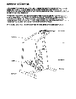
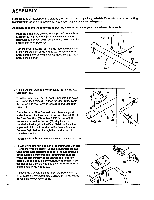
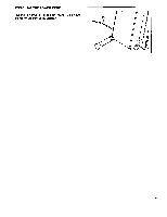
ASSEMBLY Place all partsche,stepper in a cleared area and remove the packing materials. Do not dispose of the packing materials until assembly is completed. Read each step carefully before beginning. Assembly requires the following tools: the included tool and your own adjustable wrench. 1. Make sure that there are two Endcaps (39) on the Front Stabilizer (37). (The Front Stabilizer is similar to the Rear Stabilizer [not shown], but there are holes near the ends of the Rear Stabilizer.) Turn the Front Stabilizer (37) so the indented bolt holes are toward the front of the Frame (2). Attach the Front Stabilizer to the Frame with two Carriage Bolts (28) and Stabilizer Nuts (42). 42-7 e 2 39 37 42 39 28 2. r ;ake sure that there are two Endcaps (39) on the Rear Stabilizer (38). Turn the Rear Stabilizer (38) so the indented bolt holes are toward the Frame (2). Attach the Rear Stabilizer to the Frame with two Carriage Bolts (28) and Stabilizer Nuts (42). Raise the back of the Frame (2) and place a support under it. Attach the lower end of the Left Handrail (11) to the Rear Stabilizer (38) with a 3 1/2" Screw (48). If necessary, move the Endcap (39) slightly so the Handrail is flush against the Rear Stabilizer. Rest the upper end of the Left Handrail in the Frame. Insert a Console Bolt (9) down through the Handrail to hold it in place temporarily. Attach the Right Handrail (not shown) in the same manner. 42 2 11 38 39t-48 28 3. Plug the wire extending from the Programmable Consble (1) into the Wire Harness (12). Make sure that the two tabs in the Wire Harness slide into the two grooves in the Console wire (see the inset drawing). If the wires are not connected as shown, the Programmable Console may be permanently damaged. Insert the end of the Console wire and the Wire Harness down into the hole in the Frame (2). Remove the Console Bolts (9) from the Handrails (10, 11). Attach the Programmable Console (1) to the Frame (2) with the two Console Bolts. 4 1 +>> 12 11 9 2 9 11 2 1 12 10
-
 1
1 -
 2
2 -
 3
3 -
 4
4 -
 5
5 -
 6
6 -
 7
7 -
 8
8 -
 9
9 -
 10
10 -
11
-
12
 |
 |
