Weslo Cadence 1000 Treadmill English Manual - Page 5
Assembly, Operation, Adjustment
 |
View all Weslo Cadence 1000 Treadmill manuals
Add to My Manuals
Save this manual to your list of manuals |
Page 5 highlights
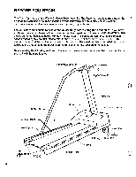
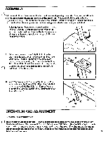
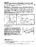
ASSEMBLY Set the treadmill in a clear area on the floor and remove all packing materials. Be sure that all parts are included before disposing of the packing materials. Please read all instructions before beginning assembly. Refer to the Part List and the Exploded Drawing on pages 10 and 11 for help in part identification. Assembly can be completed using a standard screwdriver (not included). 1. Raise the Upright Post (9) to a vertical position. Insert the Lock Knob (57), with the Lock Knob Washer (56) into the Upright Post, and turn the Knob clockwise until almost tight. Leave a little play in the Upright Post for the following steps. 9 57 56 2. Slide the upper end of the Side Rail (11) into the opening in the left side of the Console (3). Insert the Upper Side Rail Bolt (59) through the metal plate 11 3 under the Console, and tighten the Bolt into the Side Rail. Note: If the Side Rail cannot be inserted into the 10 Console far enough to attach the Bolt, roll back the Side Rail Foam (10) slightly. 3. Align the hole in the lower end of the Side Rail (11) with the hole in the Frame (30). Attach the Side Rail with the Lower Side Rail Bolt (12), Formed Washer (13) and the Side Rail Washer (14). Tighten the Lock Knob (See step 1). 14 30 OPERATION AND ADJUSTMENT GROUNDING INSTRUCTIONS This product must be grounded. If it should malfunction or break down, grounding provides a path of least resistance for electric current to reduce the risk of electric shock. This product is equipped with a cord having an equipment-grounding conductor and a grounding plug. The plug must be plugged into an appropriate outlet that is properly installed and grounded in accordance with all local codes and ordinances. 5
-
 1
1 -
 2
2 -
 3
3 -
 4
4 -
 5
5 -
 6
6 -
 7
7 -
 8
8 -
 9
9 -
 10
10 -
 11
11
 |
 |
