Weslo Cadence 1010 English Manual - Page 5
Assembly - parts
 |
View all Weslo Cadence 1010 manuals
Add to My Manuals
Save this manual to your list of manuals |
Page 5 highlights
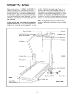
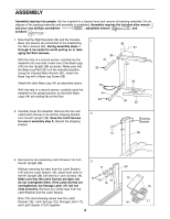
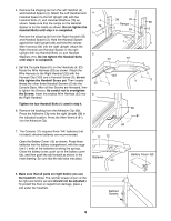
ASSEMBLY Assembly requires two people. Set the treadmill in a cleared area and remove all packing materials. Do not dispose of the packing materials until assembly is completed. Assembly requires the included allen wrench and your own phillips screwdriver , adjustable wrench , and scissors . 1. Note that the Right Handrail (32) and the Console Base (not shown) are connected to the treadmill by the Wire Harness (53). During assembly steps 1 through 5, be careful to avoid pulling on or damaging the Wire Harness. With the help of a second person, carefully lay the treadmill onto one side. Insert one of the Base Legs (44) into the Upright (38) as shown. Make sure that the Base Leg Pad (33) is in the indicated position. Using the included Allen Wrench (81), attach the Base Leg with a Base Leg Screw (39). Attach the other Base Leg (44) as described above. With the help of a second person, carefully raise the treadmill to the upright position so that both Base Legs (44) are resting flat on the floor. 1 38 44 33 44 33 39 81 53 39 32 2. Carefully lower the treadmill. Remove the two indicated Latch Screws (14) and the shipping bracket 2 from the left Upright (38). Save the Latch Screws for use in assembly step 3; discard the shipping bracket. 14 Shipping Bracket 38 3. Remove the two remaining Latch Screws (14) from the left Upright (38). 3 17 38 Without removing the tape from the Latch Bracket (16) and the Latch Spacer (13), attach both parts to the left Upright (38) with the four Latch Screws (14). Make sure that the Latch Screws are tight, but 14 13 13 do not overtighten them; if the Latch Screws are 16 overtightened, the Storage Latch (17) will not 15 slide smoothly. Remove any visible tape from the Latch Bracket and the Latch Spacer. Note: The inset drawing shows how the Latch Bracket (16), Latch Springs (15), Storage Latch (17), and Latch Spacer (13) fit together. 5 16 17
-
 1
1 -
 2
2 -
 3
3 -
 4
4 -
 5
5 -
 6
6 -
 7
7 -
 8
8 -
 9
9 -
 10
10 -
 11
11 -
12
-
13
-
14
-
15
-
16
-
17
-
18
 |
 |
