Weslo Cadence 450 English Manual - Page 7
Console Base. Make sure that the Console Cover 96 is - parts
 |
View all Weslo Cadence 450 manuals
Add to My Manuals
Save this manual to your list of manuals |
Page 7 highlights
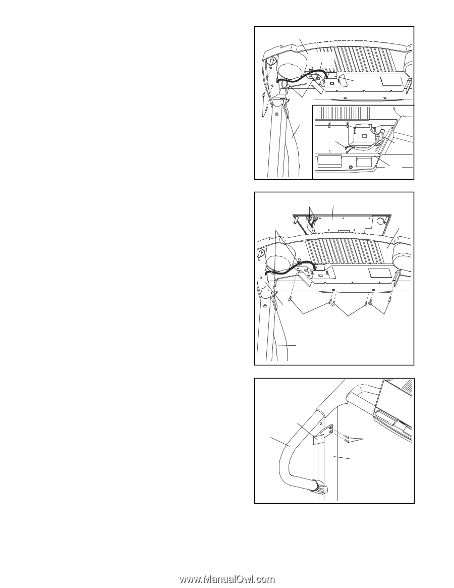
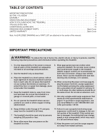
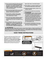
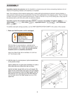
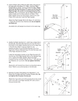
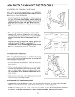
6. Place the Console Base (46) on the Right Handrail (47) 6 and the Left Handrail (not shown). Attach the Console Base with four 1 1/4" Screws (105) (only two Screws are shown). Do not tighten the Screws yet. Insert the Wire Harness (21) through the two indicated plastic ties on the Console Base (46). Next, insert the Wire Harness up through the indicated opening in the Console Base. Make sure that the Console Cover (96) is securely attached to the Console Base. 105 Refer to the inset drawing. Look at the top of the Console Base (46). Insert the Wire Harness (21) through the plastic tie on top of the Console Base. 46 21 96 Ties 47 21 Tie 46 7. Hold the Console (10) near the Console Base (46). Touch the Right Upright (62) to discharge any static. Plug the widest connector on the Wire Harness (21) into the widest connector on the Console. If the connector does not fit easily, rotate it and then connect it. Plug the other connector on the Wire Harness into the other connector on the Console. Insert the excess Wire Harness down through the opening in the Console Base. Refer to the inset drawing in step 6 above. Securely tighten the plastic tie on top of the Console Base to prevent the Wire Harness from slipping. Then, cut off the end of the plastic tie. Set the Console (10) on the Console Base (46). Insert the excess Wire Harness (21) into the large hole in the side of the Right Handrail (47). Securely tighten the plastic ties on the bottom of the Console Base to prevent the Wire Harness from slipping. Then, cut off the ends of the plastic ties. Attach the Console (10) to the Console Base (46) with two 1/2" Silver Screws (97) and four 3/4" Screws (13). Start all six Screws before tightening them; do not overtighten the Screws. 7 Ties 21 10 47 13 97 62 8 46 13 8. Attach the Storage Latch (14) to the left Upright (76) with two 3/4" Screws (13). Be careful not to overtighten the Screws. Lift the treadmill frame (see HOW TO FOLD THE TREADMILL FOR STORAGE on page 12), but do not latch it. Make sure that the frame is centered between the Handrails (1, 47 [not shown]). Firmly tighten all of the bolts and screws used in assembly steps 3, 4, 5, and 6. Then, lower the frame to the floor. 14 1 13 76 9. Make sure that all parts are properly tightened before you use the treadmill. Note: Extra hardware may be included. Keep the included allen wrenches in a secure place. The large allen wrench is used to adjust the walking belt (see page 14). To protect the floor or carpet, place a mat under the treadmill. 7
-
 1
1 -
 2
2 -
 3
3 -
 4
4 -
 5
5 -
 6
6 -
 7
7 -
 8
8 -
 9
9 -
 10
10 -
 11
11 -
 12
12 -
13
-
14
-
15
-
16
-
17
-
18
-
19
 |
 |