Weslo Cadence 60 Instruction Manual - Page 9
Set the Console 1 on the Console Base 100. Insert
 |
View all Weslo Cadence 60 manuals
Add to My Manuals
Save this manual to your list of manuals |
Page 9 highlights
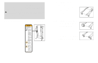
To stop the walking belt, press the Stop button. The elapsed time will begin to flash in the Time display. Note: During the first few minutes that the treadmill is used, inspect the alignment of the walking belt and align it if necessary (see page 17). 3 Follow your progress with the track and the displays. The Track-The track in the center of the console represents a distance of 200 meters. As you exercise, the indicators around the track will light in succession until the entire track is lit. The track will then darken and the indicators will again begin to light. The number of laps that you have completed will appear in the center of the track. The Time display-This display shows the elapsed time. When the Stop button is pressed, the elapsed time will flash. The Distance display- This display shows the distance that you have walked or run. The Speed display- This display shows the speed of the walking belt. The Fat Calories/ Calories/Pulse dis- Mode Indicator play-This display shows the approximate numbers of fat calories and calories you have burned (see FAT BURN- ING on page 18). The display will change from one number to the other every few seconds, as shown by the mode indica- tors. The display will also show your heart rate when you use the pulse sensor (see step 4). Note: The console can display speed and distance in either miles or kilometers. To change the system of measurement, hold down the Stop button, insert the key into the console, and continue to hold the Stop button for a moment. An "E" (for English) or an "M" (for metric) will appear in the Fat Calories/Calories/Pulse display. Press the Speed v button to change the system of measurement. When the desired system of measurement is selected, remove the key and then reinsert it. To reset the displays, press the Stop button, remove the key, and then reinsert the key. 4 Measure your heart rate if desired. To measure your heart rate, stand on the foot rails and place your thumb on the pulse sensor. Do not press too hard, or the circulation in your thumb will be restricted and your pulse will not be detected. After a few seconds, the heart-shaped indicator in the Fat Calories/Calories/Pulse display will begin to flash, one or two dashes (- -) will appear, and then your heart rate will be shown. Hold your thumb on the pulse sensor for about 15 seconds for the most accurate reading. If the displayed heart rate appears to be too high or too low, or if your heart rate is not displayed, lift your thumb off the pulse sensor for a few seconds. Then, place your thumb on the pulse sensor as described above. Remember to stand still while measuring your heart rate. 5 When you are finished exercising, remove the key. Step onto the foot rails, press the Stop button, and remove the key from the console. Keep the key in a secure place. 12 7. Hold the Console (1) near the Console Base (100). Touch the Right Handrail (6) to discharge any static. Find the connector on the end of the Wire Harness (22). Insert the connector into the red socket beneath the Console. The connector should slide easily into the socket and snap into place. If the connector does not slide easily and snap into place, turn the connector and then insert it. Make sure that the connector and wires appear as shown in drawing 7a. See drawing 5a. Insert the excess Wire Harness (22) down into the opening in the Console Base (100). Securely tighten the plastic tie on top of the Console Base to prevent the Wire Harness from slipping. Then, cut off the end of the plastic tie. 7 Ties 6 7a 22 1 100 22 8. Set the Console (1) on the Console Base (100). Insert the excess Wire Harness (22) into the large hole in the side of the Right Handrail (6). Securely tighten the plastic ties on the bottom of the Console Base to prevent the Wire Harness from slipping. Then, cut off the ends of the plastic ties. Attach the Console (1) to the Console Base (100) with four 3/4" Screws (90) and two 1/2" Screws (84). Start all six Screws before tightening them; do not overtighten the Screws. 8 1 Ties 22 6 90 84 100 90 9. Attach the Latch Housing (41) to the Left Upright (88) with two 3/4" Screws (90). Remove the Latch Knob (95) from the Latch Pin (91). Make sure that the Latch Pin Collar (93) and the Spring (94) are on the Latch Pin as shown. Insert the Latch Pin into the Latch Housing (41), and tighten the Latch Knob onto the Latch Pin. Lift the treadmill frame to the storage position (see HOW TO FOLD THE TREADMILL FOR STORAGE on page 14). Make sure that the frame is centered between the Handrails (not shown). Firmly tighten all of the bolts and screws used in assembly steps 3, 4, 5, and 8. Then, lower the frame to the floor. 9 41 95 90 88 Large Hole 94 93 91 10.Make sure that all parts are properly tightened before you use the treadmill. Note: Extra hardware may be included. Keep the included hex keyes in a secure place. The large hex key is used to adjust the walking belt (see page 17). To protect the floor or carpet, place a mat under the treadmill. Note: The underside of the treadmill walking belt is coated with high-performance lubricant. During shipping, a small amount of lubricant may be transferred to the top of the walking belt or the shipping carton. This is a normal condition and does not affect treadmill performance. If there is lubricant on top of the walking belt, simply wipe off the lubricant with a soft cloth and a mild, non-abrasive cleaner. 9
-
 1
1 -
2
-
3
-
 4
4 -
 5
5 -
 6
6 -
 7
7 -
 8
8 -
 9
9 -
 10
10 -
 11
11 -
 12
12
 |
 |
