Weslo Cadence 840 Treadmill Canadian English Manual - Page 6
Assembly - used
 |
View all Weslo Cadence 840 Treadmill manuals
Add to My Manuals
Save this manual to your list of manuals |
Page 6 highlights
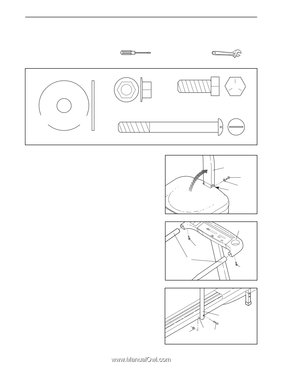
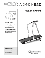
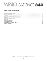
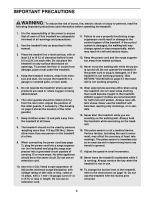
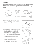
ASSEMBLY Set the treadmill in a cleared area and remove all packing materials. Do not dispose of the packing materials until assembly is completed. Refer to the drawings below to identify the small parts used in assembly. Assembly requires a standard screwdriver included). and an adjustable wrench (not 3/8" x 13/18/"2x" W1 1a/s2h"eWr asher (27)-1(27)-1 Flange Nut (54)-2 3/8" x 1" Bolt (7)-3 5/16" x 3" Bolt (71)-2 1. Raise the Upright (20) to the vertical position. Slide the 3/8" x 1 1/2" Washer (27) onto a 3/8" x 1" Bolt (7). Insert 1 the Bolt into the lower end of the Upright. Finger tighten the Bolt into the Frame (46). 20 7 27 46 2. If there are plastic ties in the upper ends of the Handrails (1), cut them off. Insert the upper end of one of the Handrails into the Console Housing (4). (Note: The two Handrails are identical. Due to the manufacturing process, there is a dimple near the lower end of each Handrail. It makes no difference which side the dimple is on when the Handrails are assembled.) Finger tighten a 3/8" x 1" Bolt (7) into the plate under the Console Housing (4) and into the Handrail. Attach the other Handrail (1) in the same manner. 3. Insert a 5/16" x 3" Bolt (71) into the lower end of the right Handrail (1) and the Frame (46). Reach under the Frame and tighten a Flange Nut (54) onto the Bolt. Attach the other Handrail (not shown) in the same manner. Tighten all Bolts used in steps 1 through 3. 6 2 4 7 1 7 3 1 54 46 71
-
 1
1 -
 2
2 -
 3
3 -
 4
4 -
 5
5 -
 6
6 -
 7
7 -
 8
8 -
 9
9 -
 10
10 -
 11
11 -
 12
12 -
13
-
14
-
15
-
16
-
17
-
18
-
19
-
20
 |
 |