Weslo Eclipse 2 Instruction Manual - Page 7
How To Use The Weslo, Eclipse Ii, Maintenance
 |
View all Weslo Eclipse 2 manuals
Add to My Manuals
Save this manual to your list of manuals |
Page 7 highlights
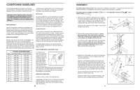
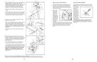
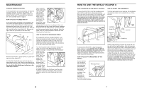
MAINTENANCE CONSOLE TROUBLE-SHOOTING If the console does not function properly, the batteries should be replaced. To replace the batteries, see assembly step 6 on page 6. In addition, make sure that the console wire is connected to the extension wire. See assembly step 6 on page 6. HOW TO ADJUST THE REED SWITCH If the console does not display correct feedback, the reed switch should be adjusted. To adjust the reed switch, the Side Shield (27) must first be removed. Remove the Crank Cover (62) and the 5/16" x 3/4" Tap Screw (18) from the left Crank Arm (10). Slide the left Crank Arm off the Crank Shaft (11). Remove the right Crank Arm (not shown) in the same way. Next, locate the Reed Switch (48). Turn the Pulley (19) until the Magnet (55) is aligned with the Reed Switch. 55 51 Loosen, but do 48 not remove, the M4 x 12mm 19 Screw (51). Slide the Reed Switch slightly toward or away from the Magnet. Make sure that the Magnet will not hit the Reed Switch. Retighten the Screw. Turn the Pulley (19) for a moment. Repeat until the console displays correct feedback. When the Reed Switch is correctly adjusted, reattach the Side Shield and the Crank Arms. Top 10 27 Back 18 11 62 42 Remove the three M4 x 16mm Screws (42) from each side of the Side Shield (27). Hold the Side Shield (27) near the back and pull it apart slightly until the Side Shield can be lifted off the ends of the Crank Shaft (11). Remove the Side Shield. Do not pull the Side Shield apart at the top or the seam may be broken. HOW TO ADJUST THE RESISTANCE STRAP If the pedals do not have enough resistance, even when the resistance knob is turned to the maximum setting, the Resistance Strap (31) may need to be adjusted. To adjust the Resistance Strap, the side shield must first be removed. Refer to the instructions at the left to remove the side shield. Turn the resistance knob to the lowest setting. (See HOW TO ADJUST THE RESISTANCE OF THE PEDALS on page 7.) Grip the end of the Resistance Strap (31) and pull it away from the rest of the Strap. Next, pull the end of the 19 Strap up to remove any 31 slack. Then press the end of the Strap against the rest of the Strap as shown. Turn the Pulley (19) for a moment to make sure that there is not too much resistance. When the Resistance Strap is properly adjusted, reattach the Side Shield and the Crank Arms. 10 HOW TO USE THE WESLO® ECLIPSE II HOW TO EXERCISE ON THE WESLO® ECLIPSE II To mount the ECLIPSE II, hold the handlebars and step onto the pedal that is in the lowest position. Next, step onto the other pedal. Push the pedals until they begin to move with a continuous motion. Note: The crank can turn in either direction; it is recommended that you turn the crank in the direction shown below; however, to give variety to your exercise, you may choose to turn the crank in the opposite direction. HOW TO ADJUST THE HANDLEBARS To further add variety to your exercise, the handlebars and extension tubes can be adjusted to any of three positions. Handlebar Spring Clip Extension Tube Lock Pin Lock Pin Holes Crank Pedal To dismount the ECLIPSE II, allow the pedals to slowly come to a stop. CAUTION: The ECLIPSE II does not have a freewheel; the pedals will continue to move until the flywheel stops. When the pedals are stationary, step off the highest pedal first. Then, step off the lowest pedal. HOW TO ADJUST THE RESISTANCE OF THE PEDALS As you exercise, you can adjust the resistance of Resistance Knob the pedals with the resistance knob mounted on the upright. To increase the resistance, turn the knob clockwise; to decrease the resistance, turn the knob counterclockwise. Pedal Leg Hold the right pedal leg. Remove the spring clip and lock pin from the right handlebar. Slide the extension tube up or down until the hole in the extension tube is aligned with a different hole in the handlebar. Reinsert the lock pin into the handlebar and the extension tube, position as shown in the inset drawing, then reattach the spring clip. Next, adjust the position of the left handlebar and extension tube. Make sure that the lock pins are inserted into the same holes in both handlebars. CAUTION: If the spring clips are not attached to the lock pins, the lock pins could slip out during use, resulting in injury to the user. 7
-
 1
1 -
 2
2 -
 3
3 -
 4
4 -
 5
5 -
 6
6 -
 7
7 -
 8
8
 |
 |
