Weslo Gym 750 Uk Manual - Page 14
Seat Assembly
 |
View all Weslo Gym 750 manuals
Add to My Manuals
Save this manual to your list of manuals |
Page 14 highlights
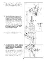
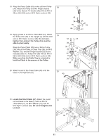
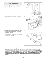
SEAT ASSEMBLY 30. Attach the Backrest (18) to the Upright (3) with two M6 x 63mm Screws (67) and two M6 Washers (73). 30 18 67 73 3 73 67 31. Attach the Seat (19), oriented as shown, to the Seat Frame (8) with four M6 x 16mm Screws (40). 31 19 Narrow End 8 40 40 32. Slide a Pad Tube (45) through the hole in the Leg 32 Lever (9). Slide two Round Pads (21) onto the ends of the Pad Tube. Repeat this step with the other Pad Tube (45) and the Seat Frame (8). 21 45 45 9 8 21 33. Make sure that all parts have been properly tightened. The use of all remaining parts will be explained in ADJUSTMENTS, on the next page. Before using the weight system, pull each cable a few times to make sure that the cables move smoothly over the pulleys. If one of the cables does not move smoothly, find and correct the problem. IMPORTANT: If the cables are not properly routed, they may be damaged when heavy weight is used. See the CABLE DIAGRAM on page 17 of this manual for proper cable routing. If there is any slack in the cables, you will need to remove it by tightening the cables; see TROUBLESHOOTING AND MAINTENANCE on page 18. 14
-
 1
1 -
2
-
3
-
4
-
5
-
6
-
7
-
8
-
 9
9 -
 10
10 -
 11
11 -
 12
12 -
 13
13 -
 14
14 -
 15
15 -
 16
16 -
 17
17 -
 18
18 -
 19
19 -
20
-
21
-
22
-
23
-
24
 |
 |
