Weslo Sprint 225 English Manual - Page 5
Drientation, Diagram, Assembly
 |
View all Weslo Sprint 225 manuals
Add to My Manuals
Save this manual to your list of manuals |
Page 5 highlights
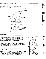
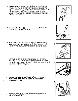
DRIENTATION DIAGRAM Before reading the following sections of this manual, please review the drawing below and familiarize yourself with the parts labeled. Tension Control Handlebar Handgrip Seat Left Side Seat Post Front Speedometer/Timer T-Wingnut Frame Flywheel Serial number decal Back Rear Leg Right Side ASSEMBLY Read all instructions carefully before beginning assembly. 2 Refer to the exploded drawing and part list on pages 10 and 11 for help with part identification. Assembly can be completed using a phillips screwdriver and an adjustable wrench. 32 5 31 1. Place all bike parts in a clear area on the floor and remove the packing materials. Make sure that all parts are included before disposing of the packing materials. 3 2. Attach the Rear Leg (31) to the Frame (5) with the two Leg Bolts (30), Molded Washers (32) and Acorn Nuts (33). 6 3. Tighten the Left Pedal (28) counterclockwise into the left arm of the Crank (6). (The shafts of the Pedals are marked with an "L" or "R" for identification purposes.) Tighten the Right Pedal 2 clockwise into the right arm of the Crank (not shown). 5
-
 1
1 -
 2
2 -
 3
3 -
 4
4 -
 5
5 -
 6
6 -
 7
7 -
 8
8 -
 9
9 -
 10
10 -
 11
11 -
12
 |
 |
