Westinghouse MT10 FLIP Installation Instructions - Page 3
Caution
 |
UPC - 882777610015
View all Westinghouse MT10 FLIP manuals
Add to My Manuals
Save this manual to your list of manuals |
Page 3 highlights
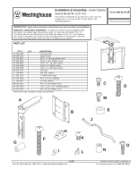
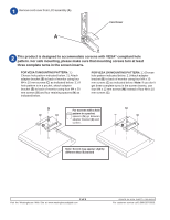
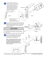
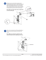
Locate the bracket in the slot so that the top of the TV does not touch the round cover or go above it when the tilt is in the open position as shown in figure 1. Place 1/4 split washer (L) on M5 screw (K) before #10 SAE washer (I) and fasten adapter plate (B) to LCD assembly (A) as shown in figure 2. Round Cover A K L I figure 1 B figure 2 Sample location: your screen may mount in a different location in the slot. Carefully hold the closed mount with the TV against the bottom of your cabinet. Make sure that there is enough clearance between the back of the TV and the wall to clear the back tab. Drill four 1/4" holes to match the A drawing to the right. Back holes of LCD assembly CAUTION Back Tab • We recommend taking the screen off the mount to Wall affix the bracket to the cabinet, to avoid any damages to the screen. Fasten LCD Assembly (A) to cabinet using four 10-32 x 1.25" screws (D) four #10 SAE washers (I) and four 1/4" spacers (E). Get all four screws (D) started before tightening. Note: If cabinet underside has lip, use four I 7/8" spacers (G) and four 10-32 x 2" screws (F) instead of screws (D) and spacers (E). This lowers LCD Assembly (A) by 7/8" to allow LCD Assembly (A) to open and close without obstruction. 6.00" 1.25" TOP VIEW D or F E or G 3 of 5 Visit the Westinghouse Web Site at www.westinghousedigital.com ISSUED: 04-16-04 SHEET #: 090-9101-1 For customer service call 1-866-287-5555.
-
 1
1 -
 2
2 -
 3
3 -
 4
4 -
 5
5
 |
 |
